8.4 - Flow rate detection
Standard unit
All units are equipped as standard with a factory-set ow switch.
It cannot be adjusted on site.
The energy transfer uid pump must be servo-controlled by the
unit: dedicated terminals are provided for installing the energy
transfer uid pump servo control (auxiliary operation switch of the
pump to be wired on site).
Unit with hydraulic module option
The “ow rate detection” functionality is handled by the option via
the pressure sensors.
8.5 - Cavitation protection (with hydraulic
module option)
To ensure the durability of pumps tted on the built-in hydraulic
modules, the control algorithm of units in the range includes
cavitation protection.
It is therefore necessary to ensure a minimum pressure of 60 kPa
(0.6 bar) at the pump inlet both when shut down and during
operation.
A pressure below 60 kPa will prevent unit start-up, or will cause
an alarm and shut-down.
A pressure below 100 kPa will trigger an alert on the user interface.
To obtain an adequate pressure, it is recommended:
■ To pressurise the hydraulic circuit between 100 kPa (1 bar) and
400 kPa (4 bar) maximum at the pump inlet;
■ To clean the hydraulic circuit during water lling or after any
modications are made;
■ To regularly clean the screen lter.
8.6 - Additional electrical heaters
Specic data 30RQ/30RQP
To compensate for the decrease in the heat pump's output at low
ambient temperatures, which changes signicantly as shown in
the graph below, it is possible to install additional electric heaters
on the unit's water outlet.
These heaters (not supplied) can be controlled via option 156.
Four outputs are available to control the switches (not supplied)
on the heaters, allowing gradual compensation of the heat pump
output reduction.
These outputs can be congured to obtain two, three or four stages
(as required), the last stage only being activated in the event of a
default shut-down of the heat pump (safety).
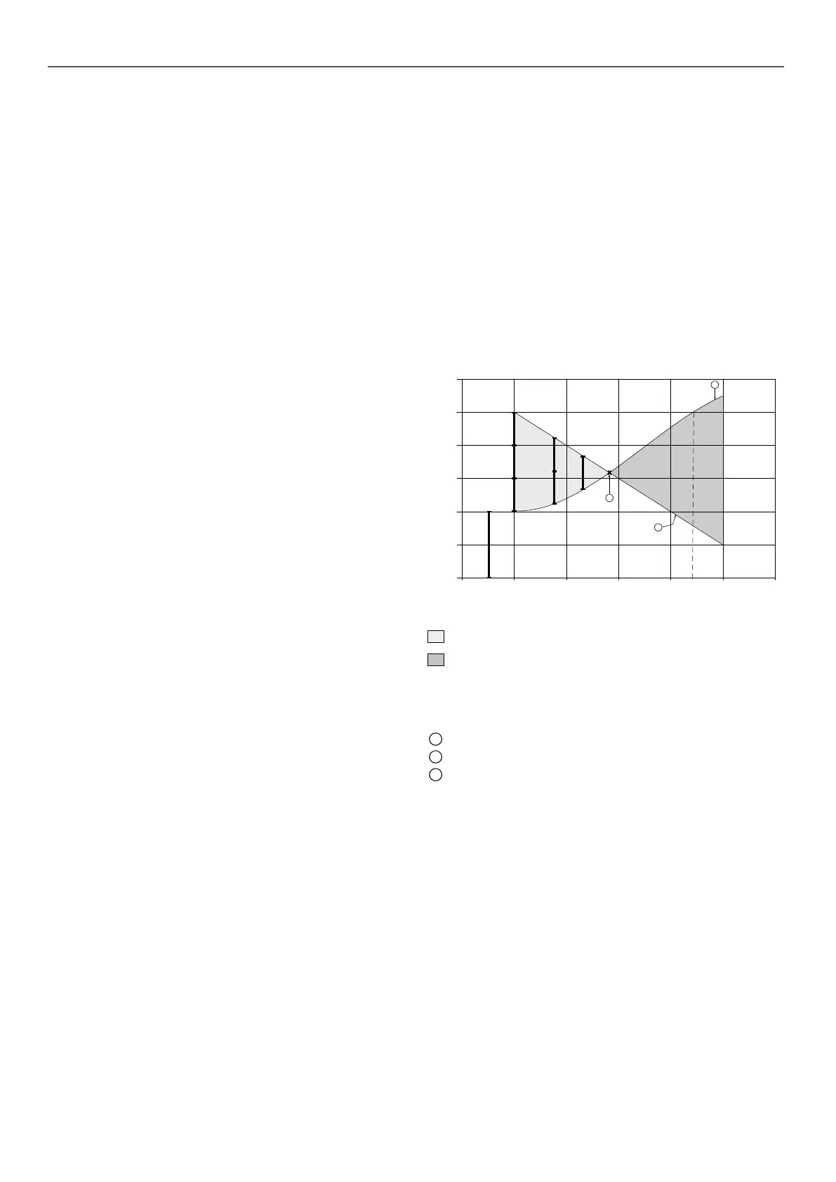
Example of additional heaters
In the graph, the power of the four heaters equals the capacity of
the heat pump at an outdoor air temperature of 7 °C.
120
100
80
60
40
20
0
-15-10 -5 05 10 15
B
B
B
C
C
D
E
A
C
B
Outdoor air (°C)
% Customer power
Operating range for which the heat pump output is less than the building heat
load
Operating range for which the heat pump output is greater than the building
heat load
B
Stage 1
C
Stage 2
D
Stage 3
E
Stage 4 (safety)
A
Variation of the heat pump output with air temperature
B
Building heat load
C
Equilibrium point between the heat pump output and the building heat load
8 - WATER CONNECTIONS
46

 Loading...

