2-10
Hardware Installation Guide for the Cisco 4000 Series Integrated Services Router
OL-32185-02
Chapter 2 Cisco 4000 Series ISRs Preinstallation
Power Guidelines and Requirements
• Ensure that the chassis cover and module rear panels are secure. All empty network module slots,
interface card slots, and power supply bays must have filler panels installed. The chassis is designed
to allow cooling air to flow within it, through specially designed cooling slots. A chassis with
uncovered openings permits air leaks, which may interrupt and reduce the flow of air across internal
components.
• Baffles can help to isolate exhaust air from intake air. Baffles also help to draw cooling air through
the chassis. The best placement of the baffles depends on the airflow patterns in the rack. You can
find the best placement by experimenting with different configurations.
• When equipment installed in a rack (particularly in an enclosed rack) fails, try operating the
equipment individually. Power off other equipment in the rack (and in adjacent racks) to allow the
router under test maximum cooling air and clean power.
Power Guidelines and Requirements
Check the power at your site to ensure that you are receiving “clean” power (free of spikes and noise).
Install a power conditioner if necessary.
The AC power supply includes the following features:
• Autoselects either 110 V or 220 V operation.
• All units include a 6-foot (1.8-meter) electrical power cord. (A label near the power inlet indicates
the correct voltage, frequency [only AC-powered systems], current draw, and power dissipation for
the unit.)
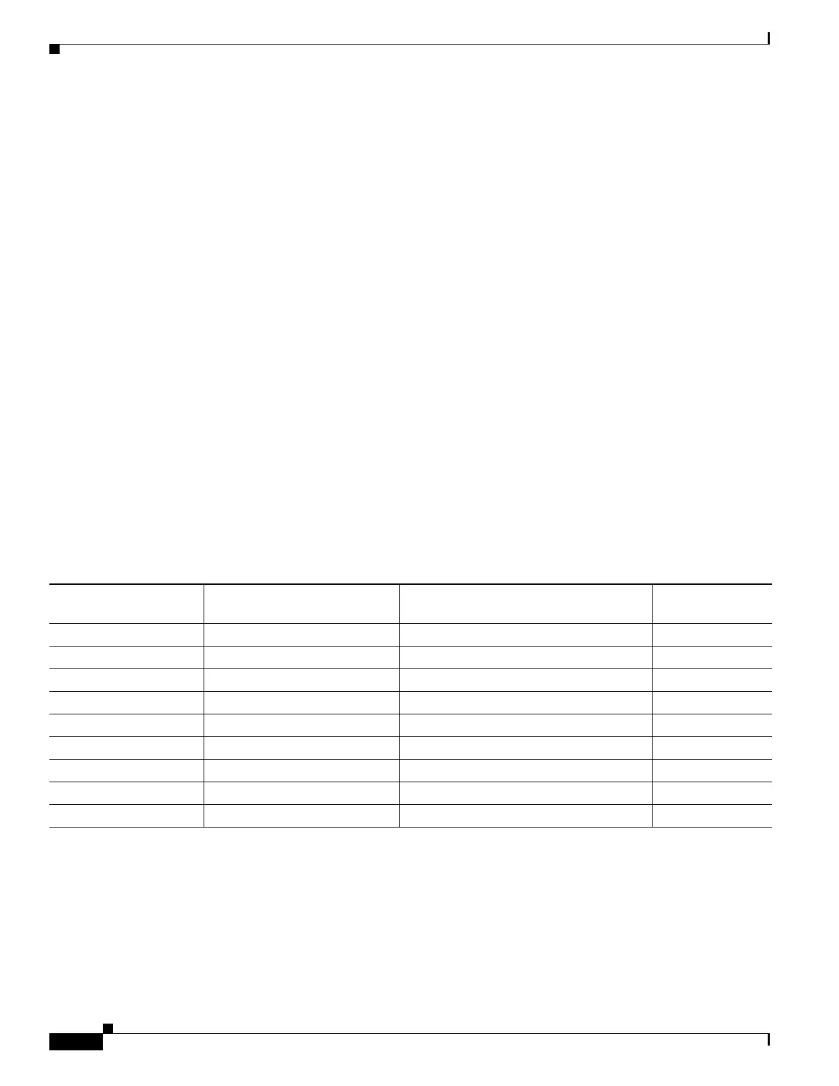
Table 2-2 lists power requirements for the Cisco 4000 Series ISRs.
Network Cabling Specifications
The following sections describe the cables required to install your Cisco 4000 Series ISRs:
• Console and Auxiliary Port Considerations, page 2-11
• Prepare for Network Connections, page 2-13
Table 2-2 Power Requirements for Cisco 4000 Series ISRs
Router Power Source Input Power Input Voltage
Tolerance Limits
Cisco 4461 ISR AC 100 — 240 VAC, 8.2 A, 50 — 60 Hz 90 — 264 VAC
Cisco 4461 with PoE AC 100 — 240 VAC, 11.0 A, 50 — 60 Hz 90 — 264 VAC
Cisco 4451 ISR AC 100 — 240 VAC, 5.3 A, 50 — 60 Hz 90 — 264 VAC
Cisco 4451 with PoE AC 100 — 240 VAC, 11.0 A, 50 — 60 Hz 90 — 264 VAC
Cisco 4431 ISR AC 100 — 240 VAC, 5.3 A, 50 — 60 Hz 90 — 264 VAC
Cisco 4351 ISR AC 100 — 240 VAC, 11.0 A, 50 — 60 Hz 90 — 264 VAC
Cisco 4331 ISR AC 100 — 240 VAC, 50 — 60 Hz 90 — 264 VAC
Cisco 4321ISR AC 100 — 240 VAC, 50 — 60 Hz 90 — 264 VAC
Cisco 4221 ISR AC 100 — 240 VAC, 50 — 60 Hz 90 — 264 VAC
 Loading...


