Figure 26: Insert the Power-Supply Module
Step 7 Use a ratcheting torque screwdriver to torque each screw to 8–10 in-lb.
Wiring the Power Source
Before you wire the power source, review these warnings:
This product relies on the building’s installation for short-circuit (overcurrent) protection. Ensure that the
protective device is rated not greater than: AC: 20 A, DC: 15 A Statement 1005
Warning
A readily accessible two-poled disconnect device must be incorporated in the fixed wiring. Statement 1022
Warning
Only trained and qualified personnel should be allowed to install or replace this equipment. Statement 1030
Warning
Hazardous voltage or energy may be present on power terminals. Always replace cover when terminals are
not in service. Be sure uninsulated conductors are not accessible when cover is in place. Statement 1086
Warning
Step 1 Ensure that the power is off at the AC or DC circuits.
Locate the circuit breakers, turn them OFF, and lock out the circuit.
If the power is not off at the AC or DC circuit breaker, do not touch the power-input terminal.
Warning
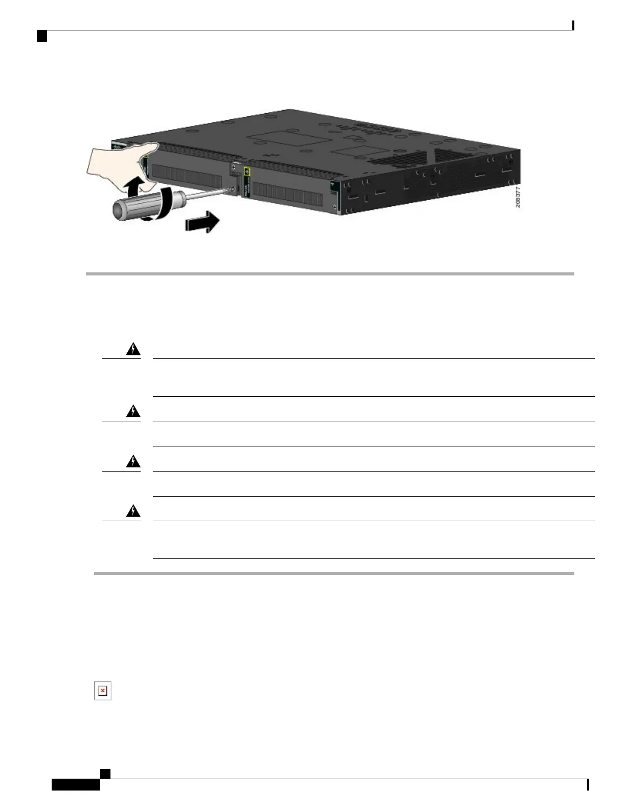
Step 2 Use a Phillips screwdriver to loosen the captive screw on the power-input terminal, and open the cover.
Figure 27: Opening the Power-Input Terminal Cover
The terminal screws labels are on the power-input terminal cover.
Cisco IE 4010 Switch Hardware Installation Guide
44
Power Supply Installation
Wiring the Power Source
 Loading...