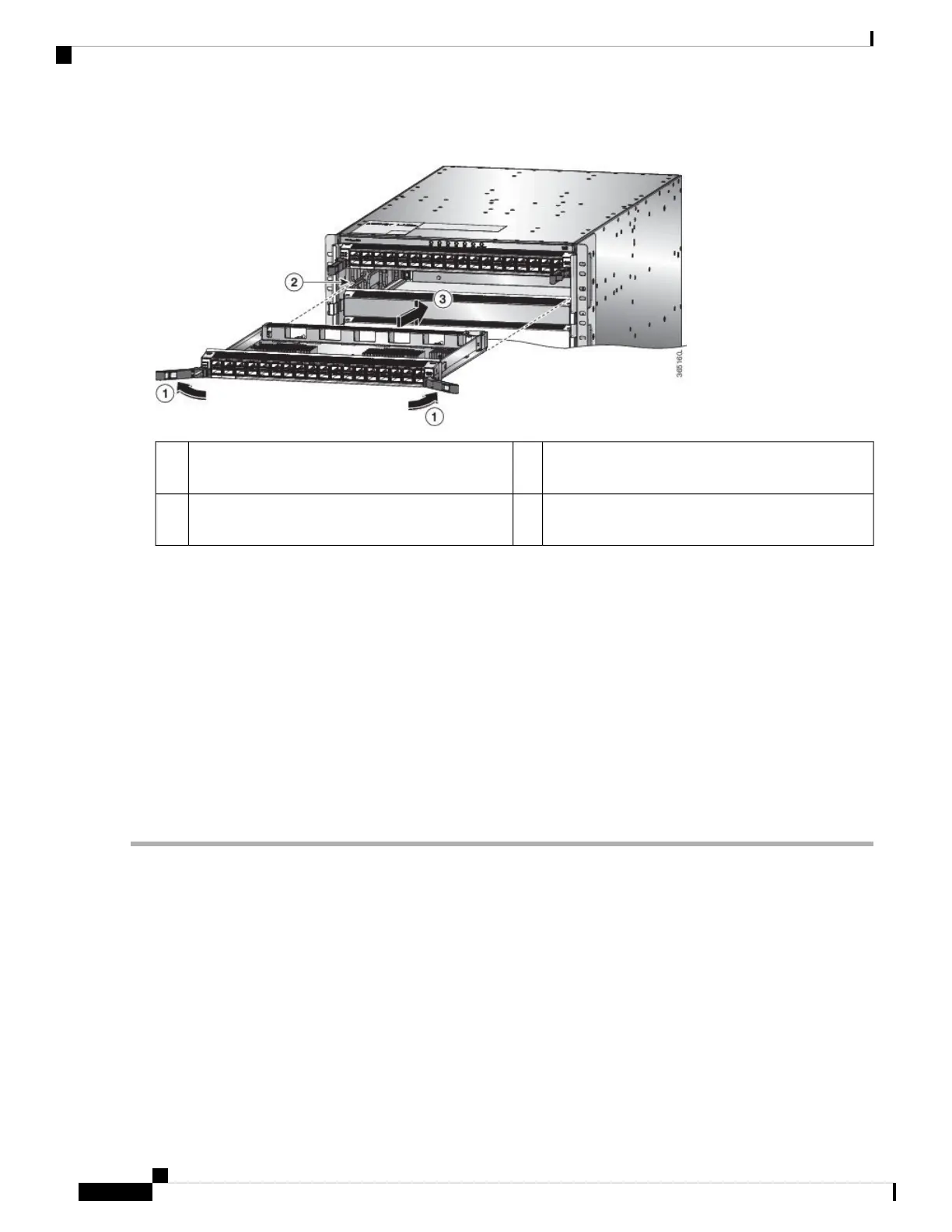
Figure 58: Insert a Line Card into the Chassis
Slide the module all the way into the slot.3Rotate the ejector handle on each end of the module
away from the center of the chassis.
1
Align the bottom of the back of the module with
tracks on either side of the slot.
2
d) Rotate the ends of the two levers toward the center of the chassis.
When the levers point straight out from the chassis, their other ends should be locked onto the brackets on the side
of the chassis.
As you rotate the levers, the front of the module moves all the way to the front of the chassis and the module fully
seats on the midplane of the chassis.
e) Attach each interface cable to the appropriate port on the line card. Use the label on each cable to determine which
port each cable attaches to.
f) Verify that the line card LEDs turn on and appear as follows:
• The Status (STS) LED blinks in amber color, then turns to solid amber color, and later turns to green color.
• For each connected port, the port LED turns on and becomes green or amber.
Installing and Removing Modular Port Adapters
The following sections describe how to install or remove MPA on the NC55-MOD-A-S and
NC55-MOD-A-SE-S line card.
Handling Modular Port Adapters
Each modular port adapter (MPA) circuit board is mounted to a metal carrier and is sensitive to electrostatic
discharge (ESD) damage.
Hardware Installation Guide for Cisco NCS 5500 Series Modular Routers
104
Replace Chassis Components
Installing and Removing Modular Port Adapters
 Loading...