Transceivers, Connectors, and Cables
Transceiver and Cable Specifications
To determine which transceivers and cables are supported by this router, refer to the Transceiver Module
Group (TMG) Compatibility Matrix Tool:
https://tmgmatrix.cisco.com/home
To see the transceiver specifications and installation information, see Cisco Transceiver Modules Install and
Upgrade Guides.
RJ-45 Connectors
The RJ-45 connector connects Category 3, Category 5, Category 5e, Category 6, or Category 6A foil twisted-pair
or unshielded twisted-pair cable from the external network to the following module interface connectors:
• Router chassis
• CONSOLE port
• MGMT ETH port
To comply with GR-1089 intrabuilding, lightning immunity requirements, you must use a foil twisted-pair
(FTP) cable that is properly grounded at both ends.
Caution
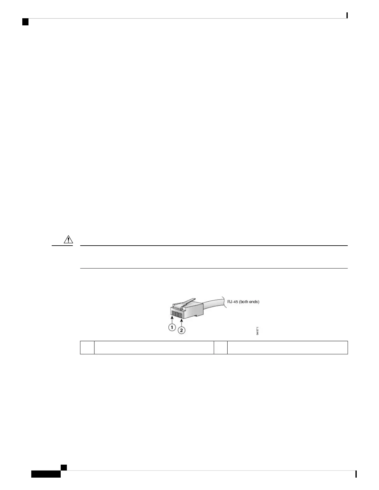
The following figure shows the RJ-45 connector.
Figure 2: RJ-45 Connector
Pin 22Pin 11
Pinouts
The following sections describe the pinouts for the Cisco NCS 5500 RP-E (NC55-RP-E) interfaces:
BITS Port Pinouts
The table below summarizes the BITS port pinouts.
Hardware Installation Guide for Cisco NCS 5500 Series Modular Routers
12
NCS 5500 Series Modular Router Overview
Transceivers, Connectors, and Cables
 Loading...