The grounding points on the chassis are sized for 10-32 screws. You must provide your own screws, grounding
lug, and grounding wire. The grounding lug must be dual-hole lug that fits 10-32 screws. The grounding cable
that you provide must be 14 AWG (2 mm), minimum 60° C wire, or as permitted by the local code.
Note
Replacing a PCIe Card
Cisco supports all PCIe cards qualified and sold by Cisco. PCIe cards not qualified or sold by Cisco are the
responsibility of the customer. Although Cisco will always stand behind and support the C-Series rack-mount
servers, customers using standard, off-the-shelf, third-party cards must go to the third-party card vendor for
support if any issue with that particular card occurs.
Note
PCIe Slot Specifications
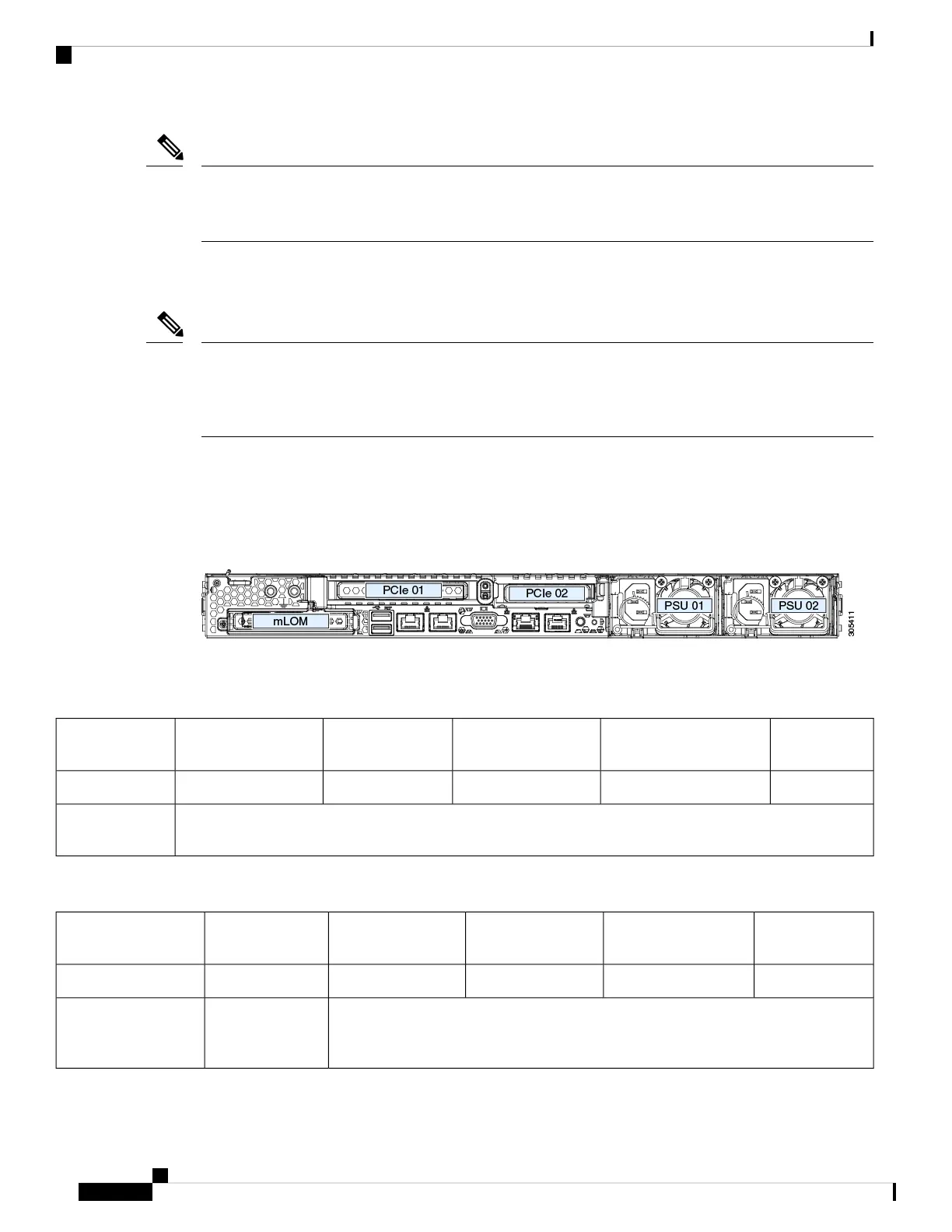
The server contains two PCIe slots on one riser assembly for horizontal installation of PCIe cards. Both slots
support the NCSI protocol and 12V standby power.
Figure 31: Rear Panel, Showing PCIe Slot Numbering
The following tables describe the specifications for the slots.
Table 6: PCIe Riser 1/Slot 1
NCSI SupportCard Height (Rear Panel
Opening)
Maximum Card
Length
Connector LengthElectrical Lane
Width
Slot Number
YesFull-height¾ lengthx24 connectorGen-3 x161
One socket for Micro SD cardMicro SD card
slot
Table 7: PCIe Riser 2/Slot 2
NCSI SupportCard Height (Rear
Panel Opening)
Maximum Card
Length
Connector LengthElectrical Lane
Width
Slot Number
Yes½ height½ lengthx24 connectorGen-3 x162
Other end of cable connects to front drive backplane to support front-panel NVMe
SSDs.
Gen-3 x8PCIe cable connector
for front-panel NVMe
SSDs
Maintaining the Server
56
Maintaining the Server
Replacing a PCIe Card
 Loading...