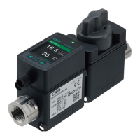
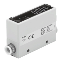
FSM3 Series
Wiring
DANGER
Use power supply voltage and output within the
specied voltage.
If voltage exceeding the specied voltage is
applied, the sensor could malfunction or be
damaged, or electrical shock or re could occur.
Do not use any load that exceeds the rated
output. Otherwise, output damage or fire may
result.
Stop the control device and equipment and turn
power OFF before wiring. Starting operation
suddenly could cause unpredictable and dangerous
operation. Conduct an energized test with controls
and machine devices stopped, and set target switch
data. Be sure to discharge any accumulated
electrostatic charge among personnel, tools, or
equipment before and during work. Connect and
wire bending resistant material, such as robot wire
material for movable sections.
Install the product and wiring away from sources of
noise, such as power distribution wires. Provide
separate countermeasures for surge applied to the
power cable. The display or output could uctuate.
Do not short-circuit the load. Failure to observe this
could result in rupture or burning.
The output impedance of the analog output section
is approx. 1 kΩ. If the impedance of the connecting
load is small, output error increases. Check error
with the impedance of the connecting load before
using. (The analog output current output is
excluded.)
Check wiring insulation.
Check that wires do not come into contact with
other circuits, that no ground faults occur, and that
the insulator between terminals is not defective.
Overcurrent could ow in and damage the sensor.
Check line color when wiring. As incorrect wiring
could result in sensor damage and malfunctions,
check wire color against the instruction manual
before wiring.
Use a stabilized DC power supply within the
specied rating that has been insulated from the AC
power supply. A non-insulated power supply could
result in electrical shock. If power is not stabilized,
the peak value could be exceeded. This could
damage the product or impair accuracy.
Do not use at levels exceeding the power supply
voltage range. If voltage exceeding this range or AC
power is applied, the controller could rupture or
burn.
Check that stress (7 N and over) is not applied to
cable leadouts or connectors.
Always attach the connector bar after connecting the
connector cover.
If switches are operated when uid is pulsating or
ow rate is otherwise unstable, operation may be
unstable. In this case, provide sufcient margin
between the two setting values and avoid setting
switches in an unstable area. Conrm that switch
operation is stable before use.
Do not turn the knob forcibly when fully closing
or opening it (0.05 N∙m or less). Do not use the
lock nut to adjust the needle. Otherwise this
could cause needle galling or damage.
The set flow rate may be unstable if turning
the dial of the needle valve forcibly when fully
closing. Do not overly tighten the dial.
FSM3- V Output impedance : Ro = 1 KΩ
Load internal impedance : Rx = 1 MΩ
Output value = (1 − ) × 100%
Ro
Ro + Rx
= (1 − ) × 100%
1 KΩ
1 KΩ + 1 MΩ
Output value
error
approx. 0.1%
Example of calculation
CAUTION
Needle valve integrated
Note that if you mount the elbow tting in a
downward position, it may interfere with the DIN rail
mounting.
Note that the bracket mounting position may
interfere with the elbow tting.
WARNING
During adjustment
CAUTION
47
LCD displayBar display
IO
-
Link
Internal
structure
Separate
display
Technical
data
Operating
method
Optional
products
Safety
precautions
Related
products
 Loading...