M0201ABK_uc ERA® WCS and e-POI Subracks and Power Supply Unit Installation Guide
© June 2021 CommScope, Inc. Page 13
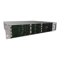
WCS-2 and WCS-4 Subrack Overview
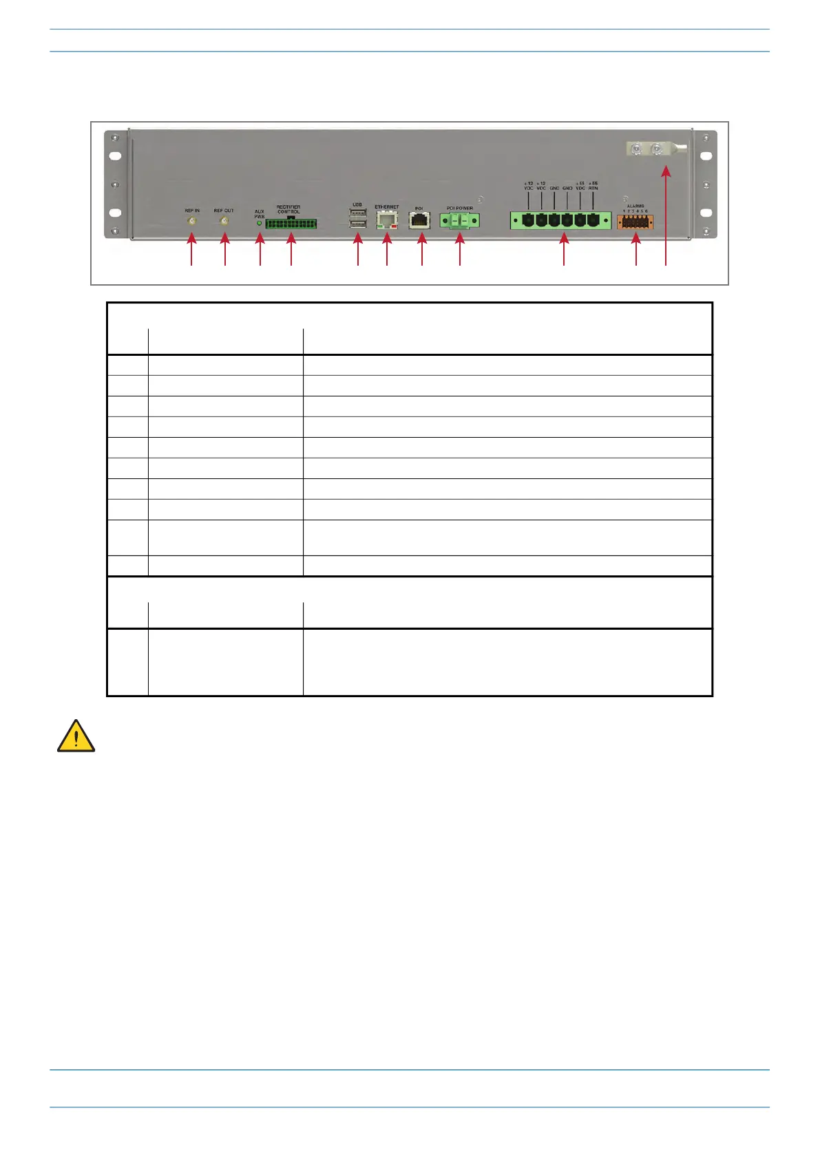
WCS Subrack Back Panel Connectors
WCS Subrack Back Panel Connectors
Ref. # Component Description
1 REF IN connector Reserved for use by CommScope.
2 REF OUT connector Reserved for use by CommScope.
4 Rectifier Control connector 24-pin connector for PSU communication
5 USB connectors Reserved for use by CommScope.
6 Ethernet connector Connects to local laptop using http://192.168.1.1/
7 POI connector Communications port that connects to the optional e-POI Subrack.
8 POI Power connector 12 Vdc to e-POI Subrack
9 Power connector Inputs to the 12 Vdc Rectifier Module and the 57 Vdc Rectifier Module
10 Alarm connector Dry contact input and output; see "-48Vdc WCS Subrack Back Panel Connectors”
on page 14.
11 Ground stud Ground (earth) connection to the Power Supply Subrack
WCS Subrack Back Panel LED
Ref # LED LED Color/Status
3 AUX PWR • On/Green when the Rectifier Control Cable is installed, and the PSU is
powered on.
• Off when either the PSU is off, or the PSU is on, but the control cable is
unplugged.
To prevent SEVERE damage to the WCS Subrack, confirm that all AC power cables are unplugged from the
rear of the PSU BEFORE plugging/unplugging the Rectifier Control cable into/from the WCS Subrack.
 Loading...