ERA® WCS and e-POI Subracks and Power Supply Unit Installation Guide M0201ABK_uc
Page 40 © June 2021 CommScope, Inc.
Optional e-POI Subracks
OPTIONAL e-POI SUBRACKS
This section provides a product overview and installation instructions for the optional ERA Series Point of
Interface (e-POI) Subrack (PN 7676311-xx). You use an e-POI Subrack to attenuate high-power RF signals
from their source to the CAN, across all frequencies.
The universal e-POI Subrack provides power, housing, and communications for up to eight e-POI Modules.
The e-POI Subrack ships with the Interface Card (IFC) factory installed. The e-POI Subrack and the Interface
Card and e-POI Module have an operating temperature range of -5 to +50 °C (+23 to +122 °F).
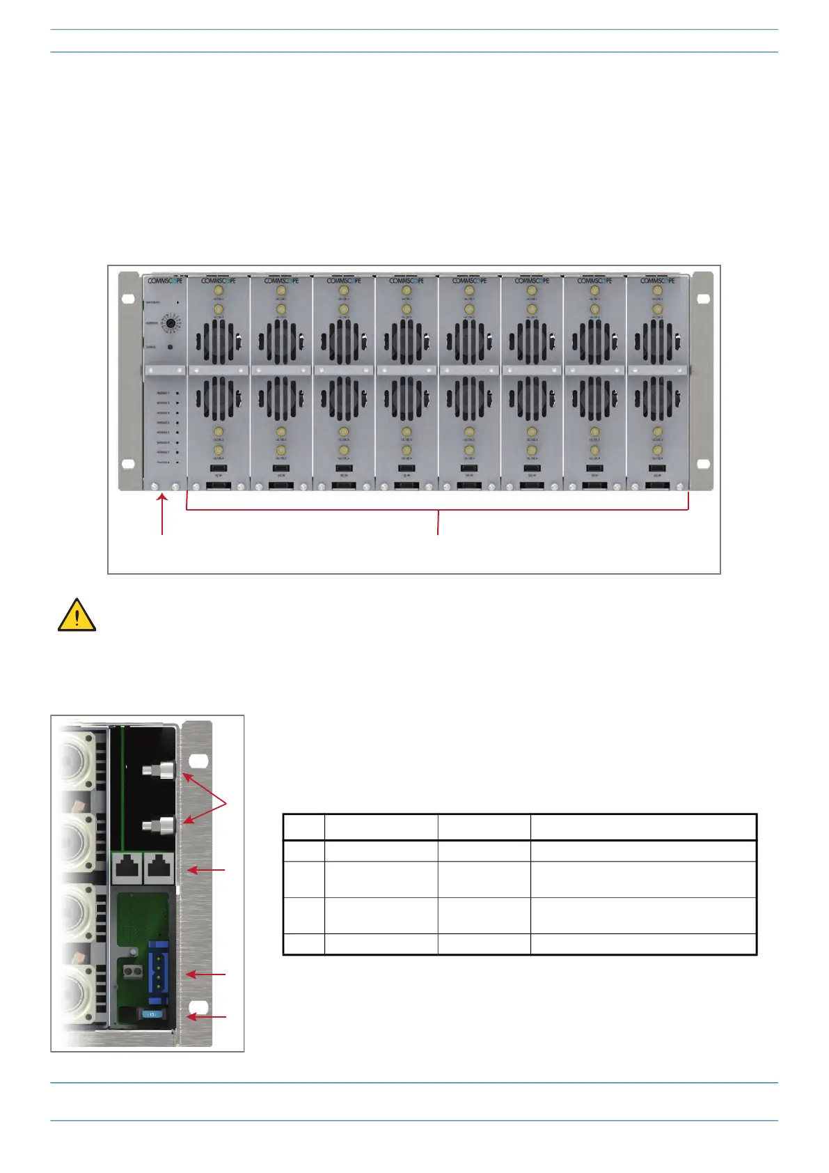
The following graphic and table identify the e-POI Subrack back-panel connectors.
To maximize airflow through the e-POI chassis, blank modules must be installed in all empty slots. If
additional ERA e-POI Blank Modules (PN 7673474-xx) are required, contact your local CommScope sales
representative.
Interface Card
(IFC)
e-POI Subrack supports up to 8 RFD Cards
Ref # Component Device Function
1 Ground studs Ground studs Provides grounding for the e-POI Subrack.
2 Communication
ports
RJ-45 jack
(female)
Communication ports that connect to the
WCS-2 or WCS-4 Subrack.
3 12 Vdc Input
connector
4-pin power
terminal
Power terminal that connects to the WCS-2
or WCS-4 Subrack.
4 15A Blade Fuse
 Loading...