ERA® WCS and e-POI Subracks and Power Supply Unit Installation Guide M0201ABK_uc
Page 64 © June 2021 CommScope, Inc.
Install and Connect the Subrack Cards
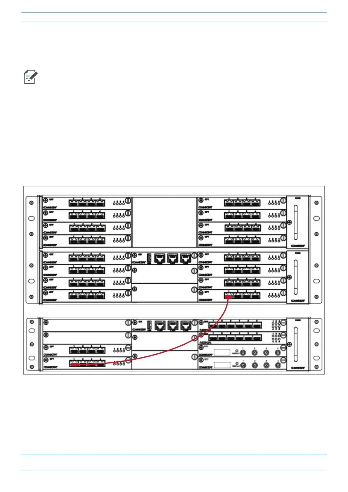
Cabling OPT Cards to Connect a WIN a Switching CAN
In this process you will connect SFP+ Modules to the fiber cable and then use the cable to connect a WIN to a
Switching CAN.
1 Complete the steps in "SFP+ Modules Tested for use with ERA” on page 62.
2 Obtain a pair of SFP+ Modules that correspond to the length and type of fiber you will use to connect the
CAN to the WIN. Note the maximum range listed inTable 13 on page 61.
3 Follow local practice or manufacturer recommendations to clean fiber connectors.
4 Connect one end of the cable with an SFP+ Module into one of the OPT Card ports (labeled 1 - 4) installed
in the Switching CAN—you can only use Slots R1 - R8 in the Switching CAN.
5 Connect the other end of the cable with an SFP+ Module into Port 1 on the OPT Card installed in Slot L1
(L1.1) of the WIN.
The graphics used in this process show a WCS-4 Subrack as a Switching CAN, and a WCS-2 Subrack as a
WIN. The same rules for slots and port connections apply if the Switching CAN was a WCS-2 Subrack or
the WIN was a WCS-4 Subrack.
WCS-4 Subrack configured as a Switching CAN
WCS-2 Subrack configured as a WIN
 Loading...