M0201ABK_uc ERA® WCS and e-POI Subracks and Power Supply Unit Installation Guide
© June 2021 CommScope, Inc. Page 61
Install and Connect the Subrack Cards
Optical Link Loss
Optical loss is calculated by adding the attenuation due to the length of the fiber optic cable, the number of
connectors in the link, and the number of splices. If there are other optical devices in the link, then their
attenuation needs to be included as well (mux, demux, add/drop, etc.).
Optical Link Loss = fiber length(km) * optical attenuation/km
+ Splice Loss * Number of splices
+ Connector Loss * Number of Connectors
Minimum Performance Levels
The values below are the minimum performance specifications for fiber optic components noted in
ANSI/TIA/EIA-568-C.3 Optical Fiber Cabling Components, with key performance specifications shown in
Table 12 and Table 13 below.
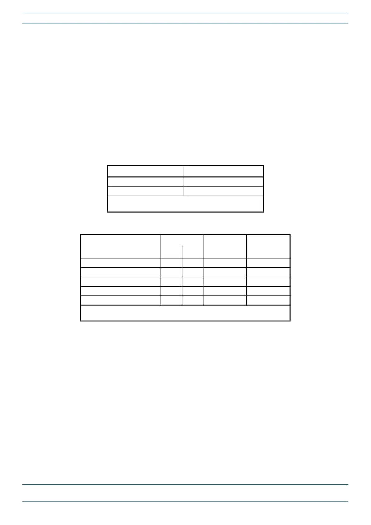
Table 12. Minimum Performance of Optical Components
Parameter Minimum Performance
1
Mated connector pair 0.75 dB
Splice 0.3 dB
1 Actual performance may be better than the minimum
performance values noted.
Table 13. 10 Gbps Ethernet Standards for Optical Link Budget
SFP+ Module Type 10GBASE-SR 10GBASE-LR 10GBASE-ER
Fiber Class OM3 OM4 G.652 G.652
Maximum Distance (m) 300 400 10,000
1
40,000
1
Wavelength of Operation (nm) 850 850 1310 1550
Loss per km @ wavelength (dB) 3.5 3.5 0.5 0.5
Allowed Measured Loss (dB) 2.6 2.9 6.0 11.0
Allowed Back Reflection (dB) -20 -20 -26 -26
1 Maximum Distance may require < 0.5dB/km loss. Most high quality single mode cables
are so rated.
 Loading...