Points of Refrigerant Control of VRV System Si30-408
24 Basic Information
3. Points of Refrigerant Control of VRV System
3.1 Cooling Operation
Subject to change of the number of operation (thermostat-on) units, capacity, air flow rate,
suction temperature, humidity change of indoor units
Load on total system changes.
Loads on every indoor machine are different.
Compressor
Capacity Control
In order to maintain the cooling capacity corresponding to the capacity of evaporator and load
fluctuation, based on the pressure detected by low pressure sensor of outdoor unit (Pe), the
compressor capacity is so controlled to put the low pressure equivalent saturation temperatures
(evaporation temperature = Te) close to target value.
Superheated
Degree Control of
Indoor Electronic
Expansion Valve
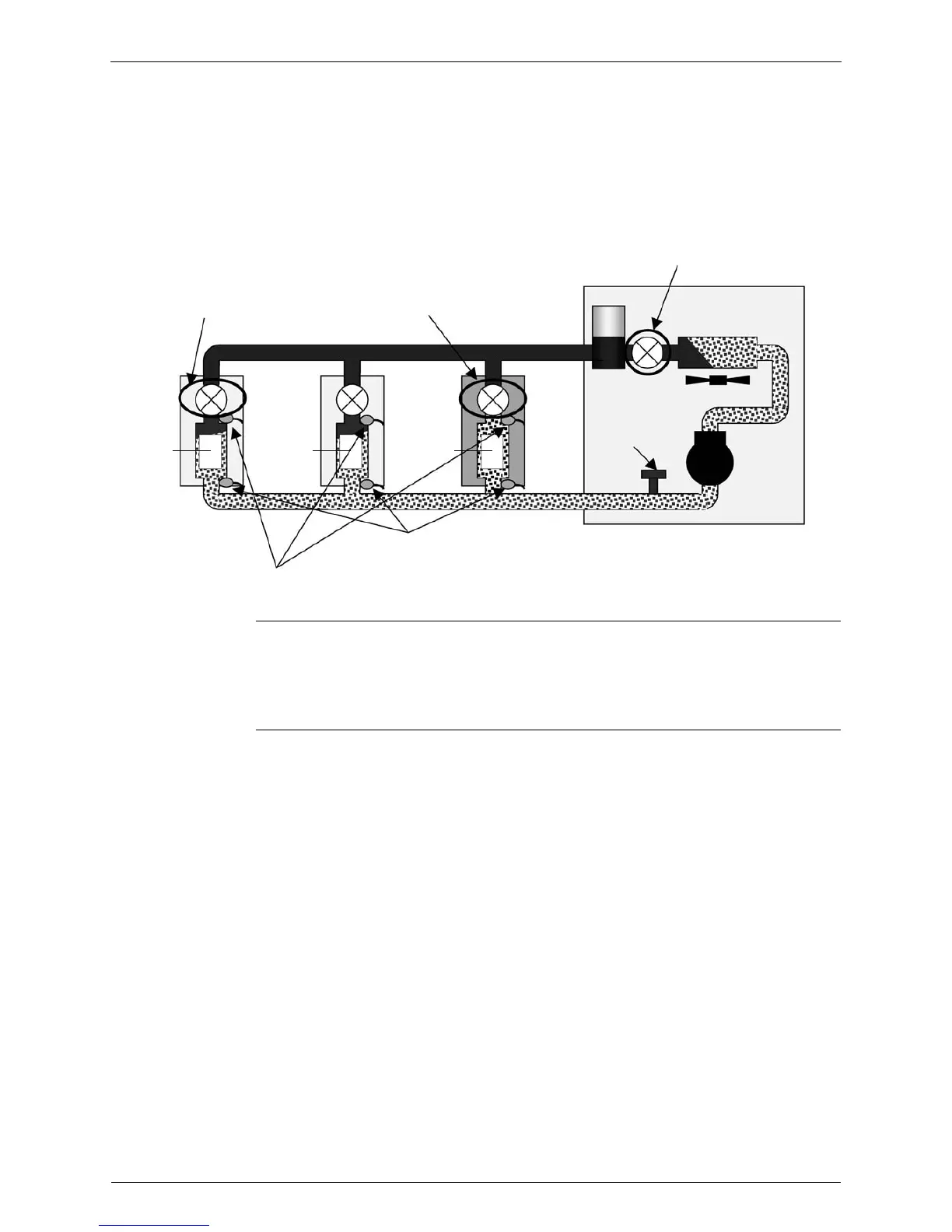
In order to maintain the superheated degree in evaporator and to distribute proper refrigerant
flow rate in spite of different loads on every indoor unit, based on the temperature detected by
thermistors of liquid pipes and gas pipes, indoor electronic expansion valve is so regulated as to
put superheated degree at evaporator outlet close to target value.
• Superheated degree SH = (indoor gas pipe temperature – indoor liquid pipe temperature)
Superheated degree control
Outdoor electronic expansion valve is fully opened.
Cooling
Compressor
Receiver
Low pressure sensor
Gas pipe themistor
Liquid pipe themistor
Operation
Operation Stop
As to stopping unit and thermostat-off unit, motorized
valve should be closed completely not to send
refrigerant into indoor heat exchanger.
 Loading...