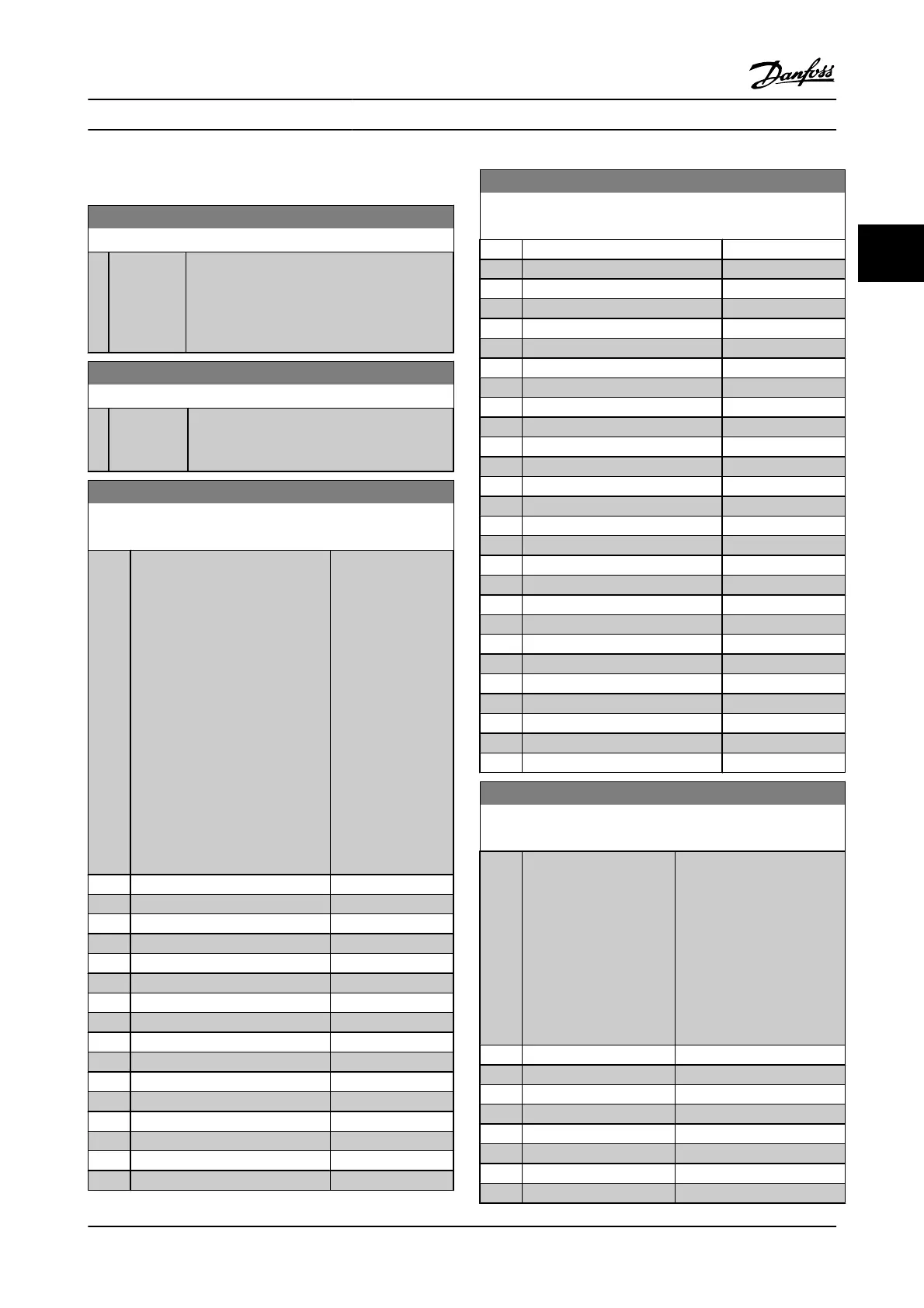
3.11 Parameters: 9-** Profibus
9-00 Setpoint
Range: Function:
0
*
[0 - 65535 ] This parameter receives cyclical reference from a
Master Class 2. If the control priority is set to
Master Class 2, the reference for the adjustable
frequency drive is taken from this parameter,
whereas the cyclical reference will be ignored.
9-07 Actual Value
Range: Function:
0
*
[0 - 65535 ] This parameter delivers the MAV for a Master
Class 2. The parameter is valid if the control
priority is set to Master Class 2.
9-15 PCD Write Configuration
Array [10]
Option: Function:
Select the
parameters to be
assigned to PCD 3 to
10 of the messages.
The number of
available PCDs
depends on the
message type. The
values in PCD 3 to 10
will then be written
to the selected
parameters as data
values. Alternatively,
specify a standard
Profibus message in
9-22 Telegram
Selection.
[0]
*
None
[302] Minimum Reference
[303] Maximum Reference
[312] Catch up/slow-down Value
[341] Ramp 1 Ramp-up Time
[342] Ramp 1 Ramp-down Time
[351] Ramp 2 Ramp-up Time
[352] Ramp 2 Ramp-down Time
[380] Jog Ramp Time
[381] Quick Stop Ramp Time
[411] Motor Speed Low Limit [RPM]
[412] Motor Speed Low Limit [Hz]
[413] Motor Speed High Limit [RPM]
[414] Motor Speed High Limit [Hz]
[416] Torque Limit Motor Mode
[417] Torque Limit Generator Mode
9-15 PCD Write Configuration
Array [10]
Option: Function:
[590] Digital & Relay Bus Control
[593] Pulse Out #27 Bus Control
[595] Pulse Out #29 Bus Control
[597] Pulse Out #X30/6 Bus Control
[653] Terminal 42 Output Bus Control
[663] Terminal X30/8 Bus Control
[673] Terminal X45/1 Bus Control
[683] Terminal X45/3 Bus Control
[748] PCD Feed Forward
[890] Bus Jog 1 Speed
[891] Bus Jog 2 Speed
[1680] Fieldbus CTW 1
[1682] Fieldbus REF 1
[1685] FC Port CTW 1
[1686] FC Port REF 1
[3310] Synchronization Factor Master (M:S)
[3311] Synchronization Factor Slave (M:S)
[3401] PCD 1 Write to MCO
[3402] PCD 2 Write to MCO
[3403] PCD 3 Write to MCO
[3404] PCD 4 Write to MCO
[3405] PCD 5 Write to MCO
[3406] PCD 6 Write to MCO
[3407] PCD 7 Write to MCO
[3408] PCD 8 Write to MCO
[3409] PCD 9 Write to MCO
[3410] PCD 10 Write to MCO
9-16 PCD Read Configuration
Array [10]
Option: Function:
Select the parameters to be
assigned to PCD 3 to 10 of the
messages. The number of
available PCDs depends on
the message type. PCDs 3 to
10 contain the actual data
values of the selected
parameters. For standard
Profibus messages, see
9-22 Telegram Selection.
[0]
*
None
[1472] VLT Alarm Word
[1473] VLT Warning Word
[1474] VLT Ext. Status Word
[1500] Operating Hours
[1501] Running Hours
[1502] kWh Counter
[1600] Control Word
Parameter Descriptions FC 300 Programming Guide
MG.33.MA.22 - VLT
®
is a registered Danfoss trademark 3-91
3
 Loading...