3.7 Parameters: 5-** Digital In/Out
3.7.1 5-0* Digital I/O Mode
Parameters for configuring the input and output using NPN
and PNP.
These parameters cannot be adjusted while motor is
running.
5-00 Digital I/O Mode
Option: Function:
Digital inputs and programmed digital outputs are pre-
programmable for operation either in PNP or NPN
systems.
[0]
*
PNP
Action on positive directional pulses (↕). PNP systems
are pulled down to GND.
[1] NPN
Action on negative directional pulses (↕). NPN systems
are pulled up to + 24 V, internally in the adjustable
frequency drive.
NOTE!
Once this parameter has been changed, it must be activated
by performing a power cycle.
5-01 Terminal 27 Mode
Option: Function:
[0]
*
Input Defines terminal 27 as a digital input.
[1] Output Defines terminal 27 as a digital output.
5-02 Terminal 29 Mode
Option: Function:
[0]
*
Input Defines terminal 29 as a digital input.
[1] Output Defines terminal 29 as a digital output.
This parameter is available for FC 302 only.
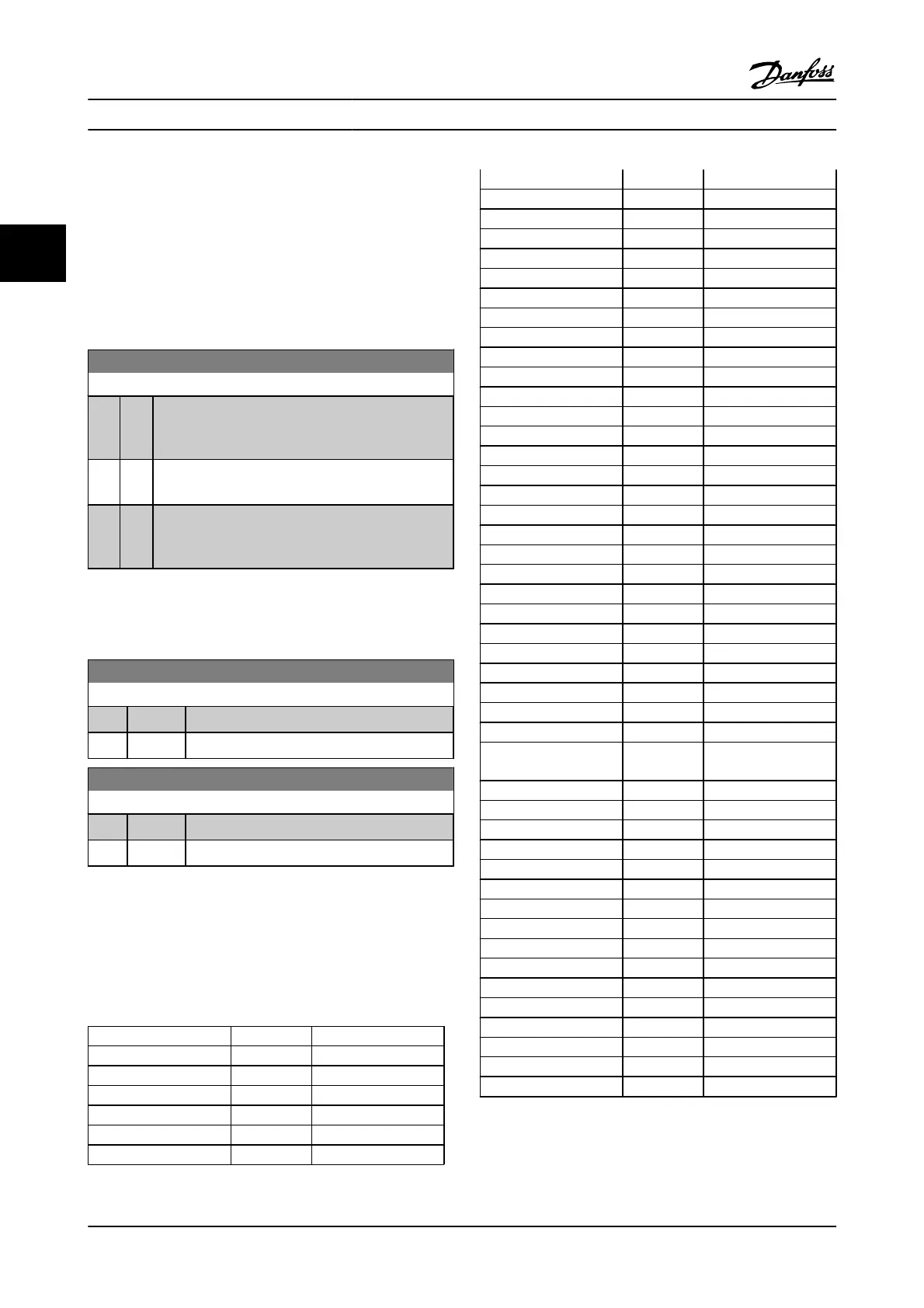
3.7.2 5-1* Digital Inputs
The digital inputs are used for selecting various functions in
the adjustable frequency drive. All digital inputs can be set
to the following functions:
Digital input function Select Terminal
No operation [0] All *term 32, 33
Reset [1] All
Coast inverse [2] All *term 27
Coast and Reset Inverse [3] All
Quick stop inverse [4] All
DC brake inverse [5] All
Stop inverse [6] All
Start [8] All *term 18
Latched start [9] All
Reverse [10] All *term 19
Start reverse [11] All
Enable start forward [12] All
Enable start reverse [13] All
Jog [14] All *term 29
Preset reference on [15] All
Preset ref bit 0 [16] All
Preset ref bit 1 [17] All
Preset ref bit 2 [18] All
Freeze reference [19] All
Freeze output [20] All
Speed up [21] All
Slow [22] All
Set-up select bit 0 [23] All
Set-up select bit 1 [24] All
Precise stop inverse [26] 18, 19
Precise start, stop [27] 18, 19
Catch up [28] All
Slow-down [29] All
Counter input [30] 29, 33
Pulse input Edge Trigged [31] 29, 33
Pulse input Time Based [32] 29, 33
Ramp bit 0 [34] All
Ramp bit 1 [35] All
Mains failure inverse [36] All
Latched precise start [40] 18, 19
Latched precise stop
inverse
[41] 18, 19
DigiPot Increase [55] All
DigiPot Decrease [56] All
DigiPot Clear [57] All
Digipot Hoist [58] All
Counter A (up) [60] 29, 33
Counter A (down) [61] 29, 33
Reset Counter A [62] All
Counter B (up) [63] 29, 33
Counter B (down) [64] 29, 33
Reset Counter B [65] All
Mech. Brake Feedb. [70] All
Mech. Brake Feedb. Inv. [71] All
PID Error Inv. [72] All
PID Reset I-part [73] All
PID enable [74] All
PTC Card 1 [80] All
FC 300 standard terminals are 18, 19, 27, 29, 32 and 33. MCB
101 terminals are X30/2, X30/3 and X30/4.
Terminal 29 functions as an output only in FC 302.
Parameter Descriptions FC 300 Programming Guide
3-48 MG.33.MA.22 - VLT
®
is a registered Danfoss trademark
3
 Loading...