VLT
®
5000 SyncPos option
MG.10.J4.02 – VLT is a registered Danfoss trade mark
10
There are two interfaces to the SyncPos option:
••
••
• 36 terminals on the option card
••
••
• 24 terminals on the VLT control card
■■
■■
■ VLT control card terminals
The terminals on the control card can be allocated
for synchronizing and positioning functions if the
following parameter settings are made:
Digital inputs 16, 17, 18, 19, 27, 29, 32 and 33:
It is always possible to read the status of the digi-
tal inputs from the SyncPos application program
with the IN command.
If Parameter 300–303 and 305–307 are set to ”No
operation” (default setting) then the inputs are
ignored by the control card but they can still be
used as inputs to the application program.
Parameter 304 can not be set to ”No operation”
which means that input 27 always has a stop func-
tion. There is one way to avoid this: Leave parame-
ter 304 at ”Coast inverse” and select ”Serial port”
in parameter 502.
Analogue inputs 53, 54 and 60:
It is always possible to read the value on the ana-
logue inputs from the SyncPos application program
with the INAD command.
If parameters 308, 311 and 314 are set to ”No ope-
ration” then the inputs are ignored by the control
card but they can still be used as inputs to the
option card.
Digital/analogue outputs 42 and 45:
Outputs 42 and 45 can be controlled from the
SyncPos application program with the OUTDA
command, when parameters 319 and 321 are set
to one of the following four settings:
OPTION DIGITAL digital output
OPTION 0 – 20 mA analogue output (default
setting)
OPTION 4 – 20 mA analogue output
OPTION 0 – 32000P pulse output
Relay outputs 01 and 04:
The relay outputs can be controlled from the
SyncPos application program with the OUT com-
mand when parameters 323 and 326 are set to the
default setting
CTRL WORD BIT 11/12
Technical data
Technical data on the control card terminals can
be found in the VLT 5000 design guide.
■■
■■
■ Option card terminals
There are two encoder interfaces which are cove-
ring the following functions:
••
••
• Feedback encoder input
••
••
• Master encoder input / virtual master output
There are 8 digital inputs, 8 digital output and ter-
minals for 5 V and 24 V supply. The functions and
technical data of the terminals are described in
the following.
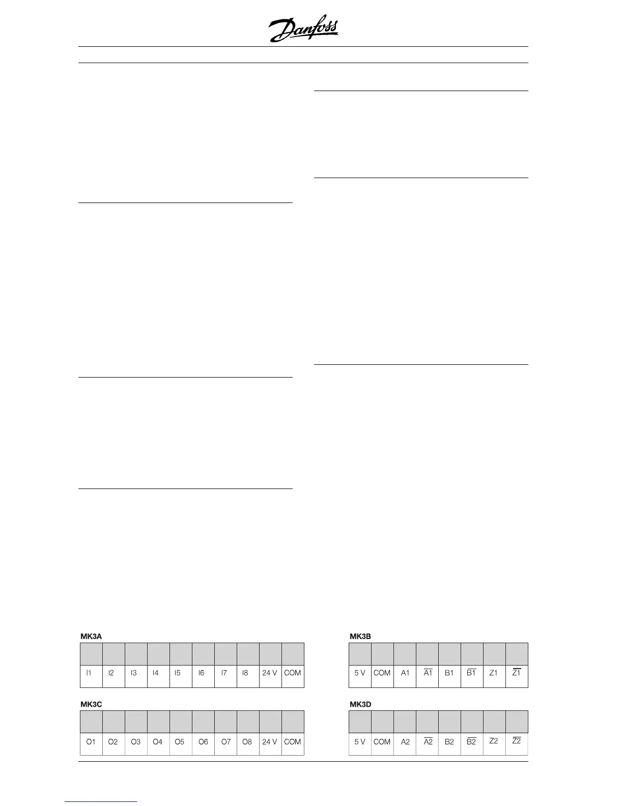
Terminal description
There are 4 terminal blocks, 2 with 10 poles and 2
with 8 poles.
(See figure below)
Input/Output terminals
Digital Inputs Master / Virtual Master
Digital Outputs Feedback
 Loading...


