13
MG.10.J4.02 – VLT is a registered Danfoss trade mark
VLT
®
5000 SyncPos option
■■
■■
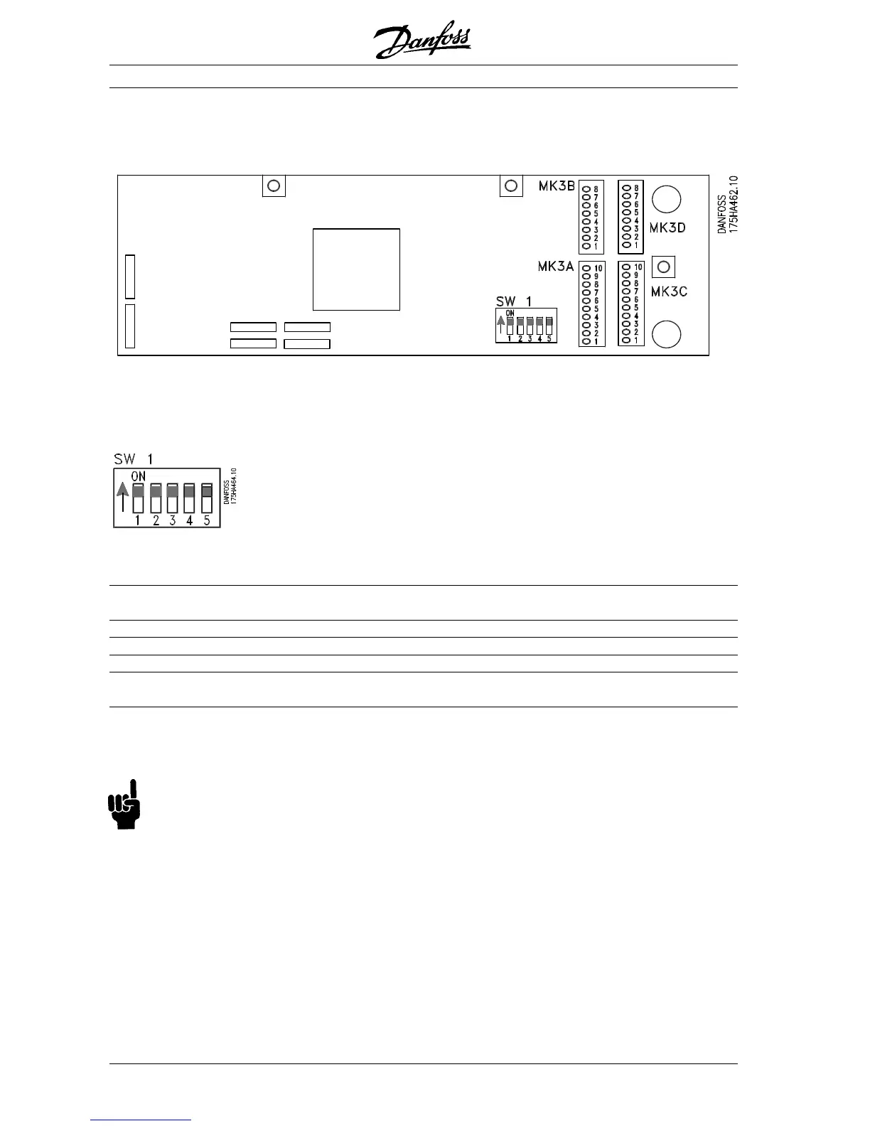
■ Option card layout:
Option card layout showing the position of connectors and dip switch.
■■
■■
■ Dip switch 1.1 – 1.5
Switch
designation OFF ON
1.1 Option card must be supplied from an Option card is supplied from control card
external power supply (24 V) (24 V)
1.2 Terminating resistor not connected (Z channel) Terminating resistor connected (Z channel)
1.3 Terminating resistor not connected (B channel) Terminating resistor connected (B channel)
1.4 Terminating resistor not connected (A channel) Terminating resistor connected (A channel)
1.5 Option card must be supplied from an Option card is supplied from control
external power supply (Common) card (Common)
Default setting of switch 1.1 - 1.5 is ON.
SW. 1.2, 1.3 and 1.4 applies only to MK3B (the master encoder interface).
NB!
When using the virtual master function termination must be switched off (sw 1.2-1.4) in all options
except on the first and the last station connected in the network. See also connection example on
page 16 and 17.
Input/Output terminals
 Loading...


