VLT
®
5000 SyncPos option
MG.10.J4.02 – VLT is a registered Danfoss trade mark
26
During booting the VLT parameters are set to the
factory settings. Only the motor parameters remain
to be set:
Perform AMA (see VLT 5000 manual) or manual
optimizing of the VLT to the connected motor.
Adjust maximum output frequency (par. 202) and
maximum reference (par. 205) according to maxi-
mum velocity of the encoder. Note that the maxi-
mum output frequency must be higher than the
frequency corresponding to maximum allowed velo-
city of the shaft because of the slip of the motor.
Terminal 27 must be connected to 24 V or parame-
ter 502 must be set to ”serial port”.
Function of inputs and output must be selected in
parameter group 3xx according to the required
functions. Note that the default values are different
from a drive without option.
Please note that parameter 780 (Dead time com-
pensation) is set to OFF (see page 111). This para-
meter is to prevent oscillation at standstill.
■■
■■
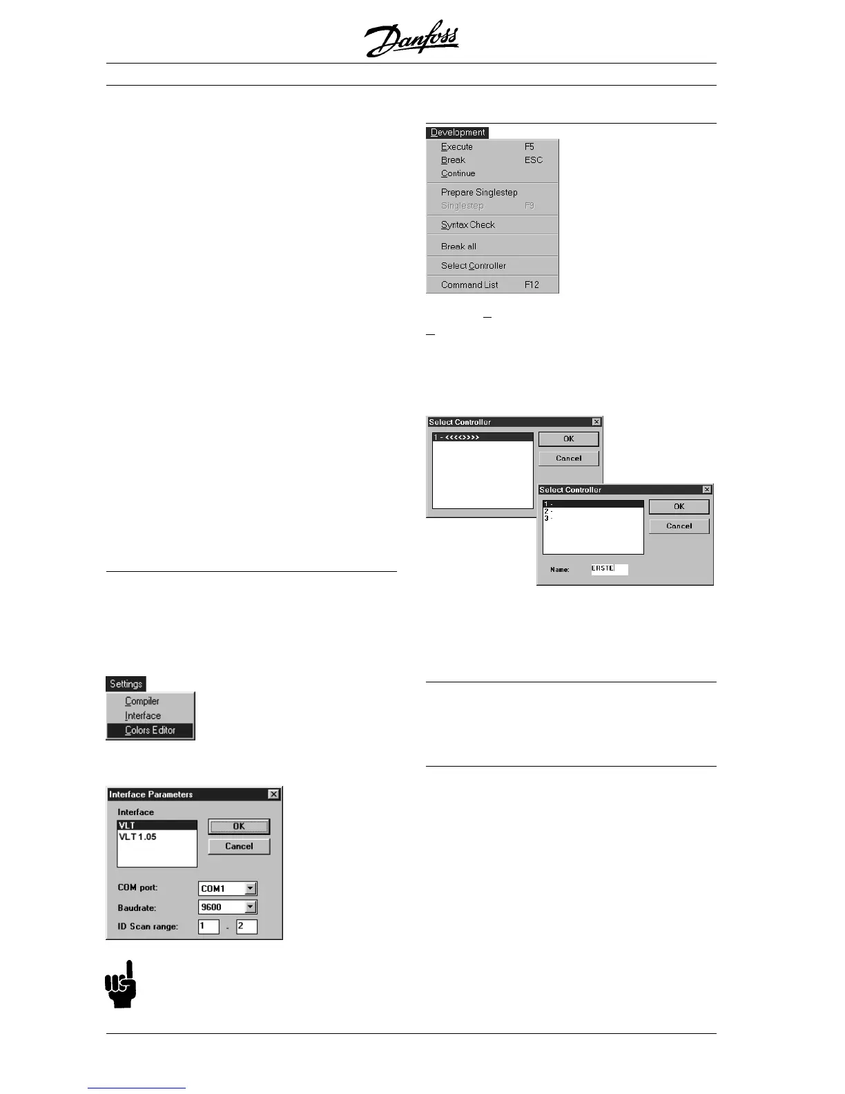
■ Setting up communication
Before you begin...
Check whether the baud rate has been set in the
VLT (par. 501); for a serial connection the baud rate
is permanently set at the factory. In this case set up
communication in your PC as follows:
Open an existing file or create a new one. Click
"SETTINGS"
→→
→→
→
"INTERFACE".
The VLT and the baud rate are pre-set. Click on
OK.
NB!
The baud rate in the VLT (Par 501) and in the
program must always agree.
"SELECT CONTROLLER"
Click on "DEVELOPMENT" → "SELECT
CONTROLLER",
in the subsequent dialog field
mark the VLT that you want to put into operation
and click on "OK"
. .
. .
. For each VLT you have connec-
ted the address set on parameter 500 will automa-
tically appear in the dialog field.
In addition to the addresses, you can also enter
names for each controller in the menu
"CONTROLLER"
→→
→→
→ "PARAMETER"
→→
→→
→ "NAME".
RS485 connection
You need the RS232 standard interface in the PC
or an additional RS232 interface card and an
external converter for a RS485 connection.
Ending communication Setup
A successful connection is reported in the commu-
nications window; the number and name of the
controller is listed in the title bar of the actual file
in addition to the file name.
Starting the SyncPos option step-by-step
■■
■■
■ Setting of VLT parameters
 Loading...


