VLT
®
5000 SyncPos option
MG.10.J4.02 – VLT is a registered Danfoss trade mark
28
RAMPMIN (31)
The
Shortest ramp Shortest ramp
Shortest ramp Shortest ramp
Shortest ramp is the time from 0 to maximum
velocity and from maximum velocity to 0. All
acceleration and deceleration commands (ACC.
DEC) are related to this value.
■■
■■
■ Setting of SyncPos option parameters: Home
Homing is not necessary in standard synchroniza-
tion applications and applications using an abso-
lute encoder.
When using an incremental encoder the controller
must be run to home after being switched on.
During this process the reference switch defines
the position at which 0 is located and how the VLT
functions during a home run: input depends on the
application.
HOME_VEL (7)
Home speedHome speed
Home speedHome speed
Home speed is entered in % relative to the
maximum speedmaximum speed
maximum speedmaximum speed
maximum speed of the drive.
You can find these values in the description of the
motor.
■■
■■
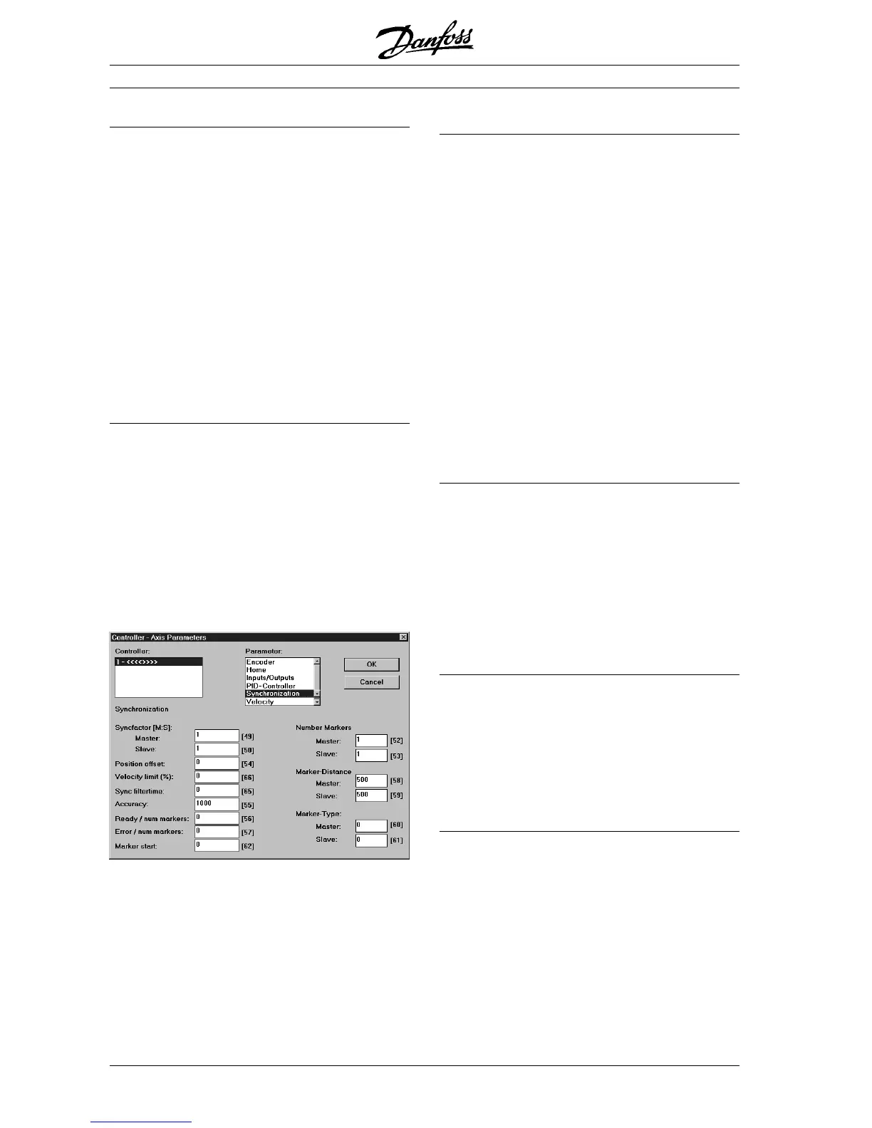
■ Setting of SyncPos option parameters:
Synchronization
The following parameters are only relevant for
synchronizing applications: Open in the menu
"CONTROLLER"
→→
→→
→ "PARAMETERS"
→→
→→
→ "AXIS" the
parameter group
Synchronization.Synchronization.
Synchronization.Synchronization.
Synchronization.
SYNCFACTM (49) and SYNCFACTS (50)
The
Synchronizing factors master Synchronizing factors master
Synchronizing factors master Synchronizing factors master
Synchronizing factors master and
slave slave
slave slave
slave
SYNCFACTM and SYNCFACTS must be set accor-
ding to the gear ratio between master and slave
encoder.
Example: Both encoders has 1024 ppr, master is
running 305 RPM and slave must run 1220 RPM.
SYNCFACTM = 305 and
SYNCFACTS = 1220.
Alternative: SYNCFACTM = 1
SYNCFACTS = 4.
The following parameters are only relevant when
using synchronizing with marker correction
(SYNCM).
Open the parameter group
SynchronizationSynchronization
SynchronizationSynchronization
Synchronization in the
menu "CONTROLLER"
→→
→→
→ "PARAMETERS"
→→
→→
→
"AXIS":
SYNCMARKM (52) and SYNCMARKS (53)
Number of master marker pulses and number of
slave marker pulses.
SYNCMARKM and SYNCMARKS must be set
according to the ratio between the number of
marker signals from master and slave. A ratio of
1:1 means that each slave marker will be aligned
with each master marker. A ratio of 2:1 means that
each slave marker will be aligned with each
second master marker.
SYNCMPULSM (58) and SYNCMPULSS (59)
When using the encoder zero pulse as marker
signal the distance between 2 markers is the reso-
lution (qc) of the encoder.
When external marker signals are used, the marker
distance can be measured by means of the pro-
gram sample "Marker count" (see chapter 7) if it is
unknown.
SYNCMTYPM (60) and SYNCMTYPS (61)
Master marker type and Slave marker type.
Master marker signal: Input 5.
Slave marker signal: Input 6
Marker signal type must be selected for master
and slave:
0 = index pulse (positive flank)
1 = index pulse (negative flank)
2 = external marker (positive flank)
3 = external marker (negative flank)
 Loading...


