parameter 2-12 Brake Power Limit (kW). Parameter 2-13 Brake
Power Monitoring selects what function occurs when the
power transmitted to the brake resistor exceeds the limit
set in parameter 2-12 Brake Power Limit (kW).
NOTICE
Monitoring the brake power is not a safety function; a
thermal switch connected to an external contactor is
required for that purpose. The brake resistor circuit is
not ground leakage protected.
Overvoltage control (OVC) can be selected as an alternative
brake function in parameter 2-17 Over-voltage Control. This
function is active for all units and ensures that if the DC-
link voltage increases, the output frequency also increases
to limit the voltage from the DC link, which avoids a trip.
NOTICE
OVC cannot be activated when running a PM motor,
while parameter 1-10 Motor Construction is set to [1] PM
non-salient SPM.
10.9 Residual Current Devices (RCD) and
Insulation Resistance Monitor (IRM)
Use RCD relays, multiple protective grounding, or
grounding as extra protection, provided they comply with
local safety regulations.
If a ground fault appears, a DC current can develop in the
faulty current. If RCD relays are used, local regulations
must be observed. Relays must be suitable for protection
of 3-phase equipment with a bridge rectier and for a brief
discharge on power-up. See chapter 10.10 Leakage Current
for more details.
10.10
Leakage Current
Follow national and local codes regarding protective
grounding of equipment where leakage current exceeds
3.5 mA.
Drive technology implies high-frequency switching at high
power. This high-frequency switching generates a leakage
current in the ground connection.
The ground leakage current is made up of several contri-
butions and depends on various system congurations,
including:
•
RFI ltering.
•
Motor cable length.
•
Motor cable shielding.
•
Drive power.
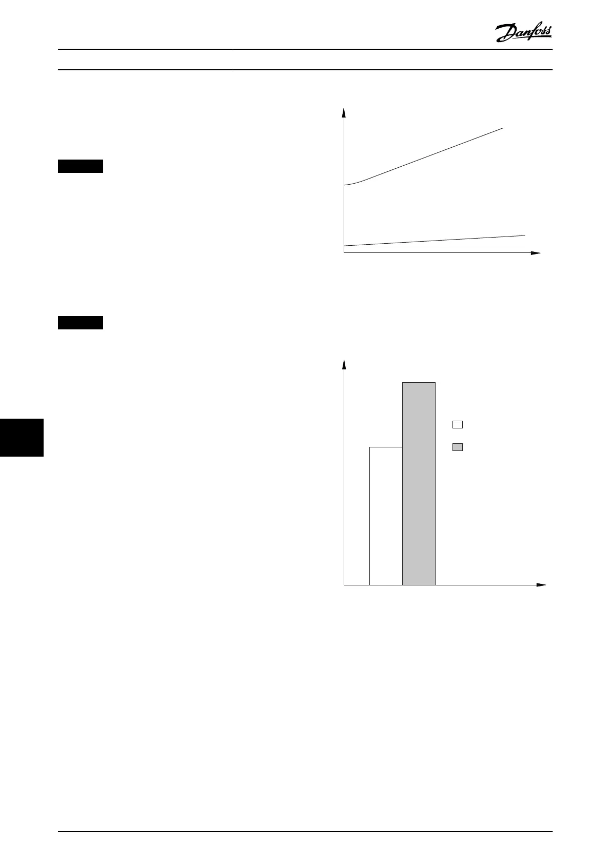
130BB955.12
a
b
Leakage current
Motor cable length
Illustration 10.21 Motor Cable Length and Power Size
Inuence the Leakage Current. Power Size a > Power Size b.
The leakage current also depends on the line distortion.
Illustration 10.22 Line Distortion Inuences Leakage Current
If the leakage current exceeds 3.5 mA, compliance with
EN/IEC61800-5-1 (power drive system product standard)
requires special care.
Reinforce grounding with the following protective ground
connection requirements:
•
Ground wire (terminal 95) of at least 10 mm
2
(8 AWG) cross-section.
•
2 separate ground wires both complying with the
dimensioning rules.
See EN/IEC61800-5-1 and EN 50178 for further information.
Electrical Installation Con...
VLT
®
HVAC Drive FC 102
188 Danfoss A/S © 11/2017 All rights reserved. MG16C302
1010
 Loading...


