14 Appendix
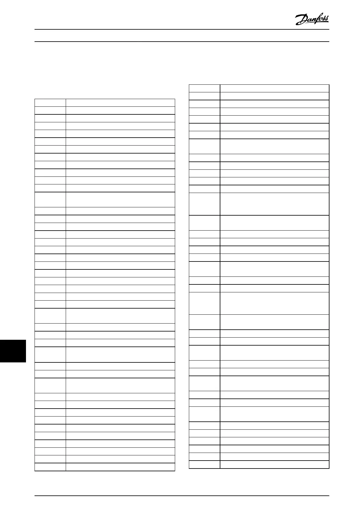
14.1 Abbreviations and Symbols
60° AVM 60° asynchronous vector modulation
A Ampere/AMP
AC Alternating current
AD Air discharge
AEO Automatic energy optimization
AI Analog input
AIC Ampere interrupting current
AMA Automatic motor adaptation
AWG American wire gauge
°C
Degrees Celsius
CB Circuit breaker
CD Constant discharge
CDM Complete drive module: The drive, feeding
section, and auxiliaries
CE European conformity (European safety standards)
CM Common mode
CT Constant torque
DC Direct current
DI Digital input
DM Dierential mode
D-TYPE Drive dependent
EMC Electromagnetic compatibility
EMF Electromotive force
ETR Electronic thermal relay
°F
Degrees Fahrenheit
f
JOG
Motor frequency when jog function is activated
f
M
Motor frequency
f
MAX
Maximum output frequency that the drive applies
on its output
f
MIN
Minimum motor frequency from the drive
f
M,N
Nominal motor frequency
FC Frequency converter (drive)
HIPERFACE
®
HIPERFACE
®
is a registered trademark by
Stegmann
HO High overload
Hp Horse power
HTL HTL encoder (10–30 V) pulses - High-voltage
transistor logic
Hz Hertz
I
INV
Rated inverter output current
I
LIM
Current limit
I
M,N
Nominal motor current
I
VLT,MAX
Maximum output current
I
VLT,N
Rated output current supplied by the drive
kHz Kilohertz
LCP Local control panel
Lsb Least signicant bit
m Meter
mA Milliampere
MCM Mille circular mil
MCT Motion control tool
mH Inductance in milli Henry
mm Millimeter
ms Millisecond
Msb Most signicant bit
η
VLT
Eciency of the drive dened as ratio between
power output and power input
nF Capacitance in nano Farad
NLCP Numerical local control panel
Nm Newton meter
NO Normal overload
n
s
Synchronous motor speed
Online/
Oine
Parameters
Changes to online parameters are activated
immediately after the data value is changed
P
br,cont.
Rated power of the brake resistor (average power
during continuous braking)
PCB Printed circuit board
PCD Process data
PDS Power drive system: CDM and a motor
PELV Protective extra low voltage
P
m
Drive nominal output power as high overload
(HO)
P
M,N
Nominal motor power
PM motor Permanent magnet motor
Process PID PID (proportional integrated dierential) regulator
that maintains the speed, pressure, temperature,
and so on
R
br,nom
Nominal resistor value that ensures a brake power
on the motor shaft of 150/160% for 1 minute
RCD Residual current device
Regen Regenerative terminals
R
min
Minimum allowed brake resistor value by the
drive
RMS Root average square
RPM Revolutions per minute
R
rec
Recommended brake resistor resistance of
Danfoss brake resistors
s Second
SCCR Short-circuit current rating
SFAVM Stator ux-oriented asynchronous vector
modulation
STW Status word
SMPS Switch mode power supply
THD Total harmonic distortion
T
LIM
Torque limit
TTL TTL encoder (5 V) pulses - transistor logic
U
M,N
Nominal motor voltage
Appendix
VLT
®
HVAC Drive FC 102
224 Danfoss A/S © 11/2017 All rights reserved. MG16C302
1414
 Loading...


