10.17 Harmonics Overview
Non-linear loads such as found with drives do not draw
current uniformly from the power line. This non-sinusoidal
current has components which are multiples of the basic
current frequency. These components are referred to as
harmonics. It is important to control the total harmonic
distortion on the mains supply. Although the harmonic
currents do not directly aect electrical energy
consumption, they generate heat in wiring and
transformers that can aect other devices on the same
power line.
10.17.1 Harmonic Analysis
Since harmonics increase heat losses, it is important to
design systems with harmonics in mind to prevent
overloading the transformer, inductors, and wiring. When
necessary, perform an analysis of the system harmonics to
determine equipment eects.
A non-sinusoidal current is transformed with a Fourier
series analysis into sine-wave currents at dierent
frequencies, that is, dierent harmonic currents I
N
with
50 Hz or 60 Hz as the basic frequency.
Abbreviation Description
f
1
Basic frequency (50 Hz or 60 Hz)
I
1
Current at the basic frequency
U
1
Voltage at the basic frequency
I
n
Current at the n
th
harmonic frequency
U
n
Voltage at the n
th
harmonic frequency
n Harmonic order
Table 10.43 Harmonics-related Abbreviations
Basic
current (I
1
)
Harmonic current (I
n
)
Current I
1
I
5
I
7
I
11
Frequency 50 Hz 250 Hz 350 Hz 550 Hz
Table 10.44 Basic Currents and Harmonic Currents
Current Harmonic current
I
RMS
I
1
I
5
I
7
I
11-49
Input current 1.0 0.9 0.5 0.2 <0.1
Table 10.45 Harmonic Currents vs. RMS Input Current
The voltage distortion on the mains supply voltage
depends on the size of the harmonic currents multiplied
by the mains impedance for the frequency in question. The
total voltage distortion (THDi) is calculated based on the
individual voltage harmonics using this formula:
THDi
=
U25 + U27 + ... + U2n
U
10.17.2 Eect of Harmonics in a Power
Distribution System
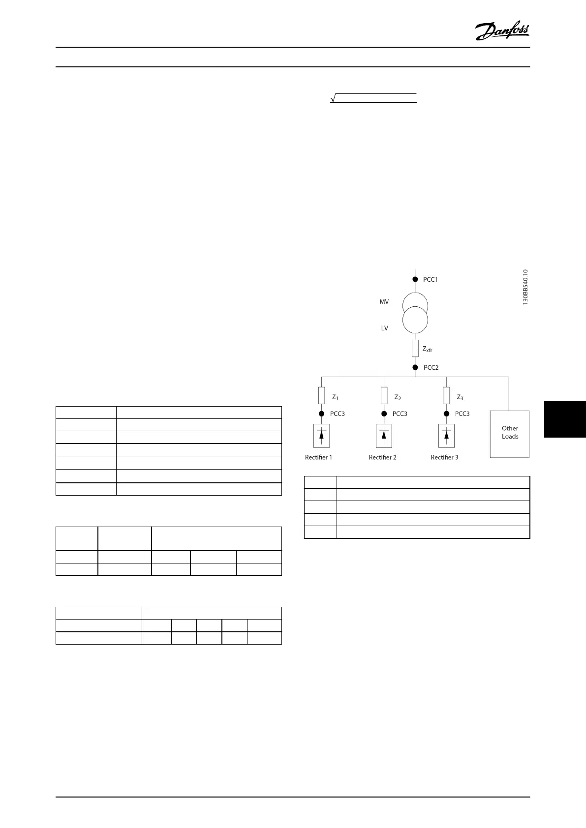
In Illustration 10.29, a transformer is connected on the
primary side to a point of common coupling PCC1, on the
medium voltage supply. The transformer has an impedance
Z
xfr
and feeds several loads. The point of common coupling
where all loads are connected is PCC2. Each load connects
through cables that have an impedance Z
1
, Z
2
, Z
3
.
PCC Point of common coupling
MV Medium voltage
LV Low voltage
Z
xfr
Transformer impedance
Z
#
Modeling resistance and inductance in the wiring
Illustration 10.29 Small Distribution System
Harmonic currents drawn by non-linear loads cause
distortion of the voltage because of the voltage drop on
the impedances of the distribution system. Higher
impedances result in higher levels of voltage distortion.
Current distortion relates to apparatus performance and it
relates to the individual load. Voltage distortion relates to
system performance. It is not possible to determine the
voltage distortion in the PCC knowing only the harmonic
performance of the load. To predict the distortion in the
PCC, the conguration of the distribution system and
relevant impedances must be known.
Electrical Installation Con... Design Guide
MG16C302 Danfoss A/S © 11/2017 All rights reserved. 197
10 10
 Loading...


