12.10 Wiring Conguration for a Relay Set-
up with Smart Logic Control
Parameters
FC
+24 V
+24 V
D IN
D IN
D IN
COM
D IN
D IN
D IN
D IN
+10 V
A IN
A IN
COM
A OUT
COM
R1R2
12
13
18
19
20
27
29
32
33
37
50
53
54
55
42
39
01
02
03
04
05
06
130BB839.10
Function Setting
Parameter 4-30
Motor Feedback
Loss Function
[1] Warning
Parameter 4-31
Motor Feedback
Speed Error
100 RPM
Parameter 4-32
Motor Feedback
Loss Timeout
5 s
Parameter 7-00 S
peed PID
Feedback Source
[2] MCB 102
Parameter 17-11
Resolution (PPR)
1024*
Parameter 13-00
SL Controller
Mode
[1] On
Parameter 13-01
Start Event
[19] Warning
Parameter 13-02
Stop Event
[44] Reset key
Parameter 13-10
Comparator
Operand
[21] Warning
no.
Parameter 13-11
Comparator
Operator
[1] ≈ (equal)*
Parameter 13-12
Comparator
Value
90
Parameter 13-51
SL Controller
Event
[22]
Comparator 0
Parameter 13-52
SL Controller
Action
[32] Set digital
out A low
Parameter 5-40 F
unction Relay
[80] SL digital
output A
*=Default value
Notes/comments:
If the limit in the feedback monitor is exceeded, warning 90,
Feedback Mon. is issued. The SLC monitors warning 90, Feedback
Mon. and if the warning becomes true, relay 1 is triggered.
External equipment may require service. If the feedback error
goes below the limit again within 5 s, the drive continues and
the warning disappears. Reset relay 1 by pressing [Reset] on the
LCP.
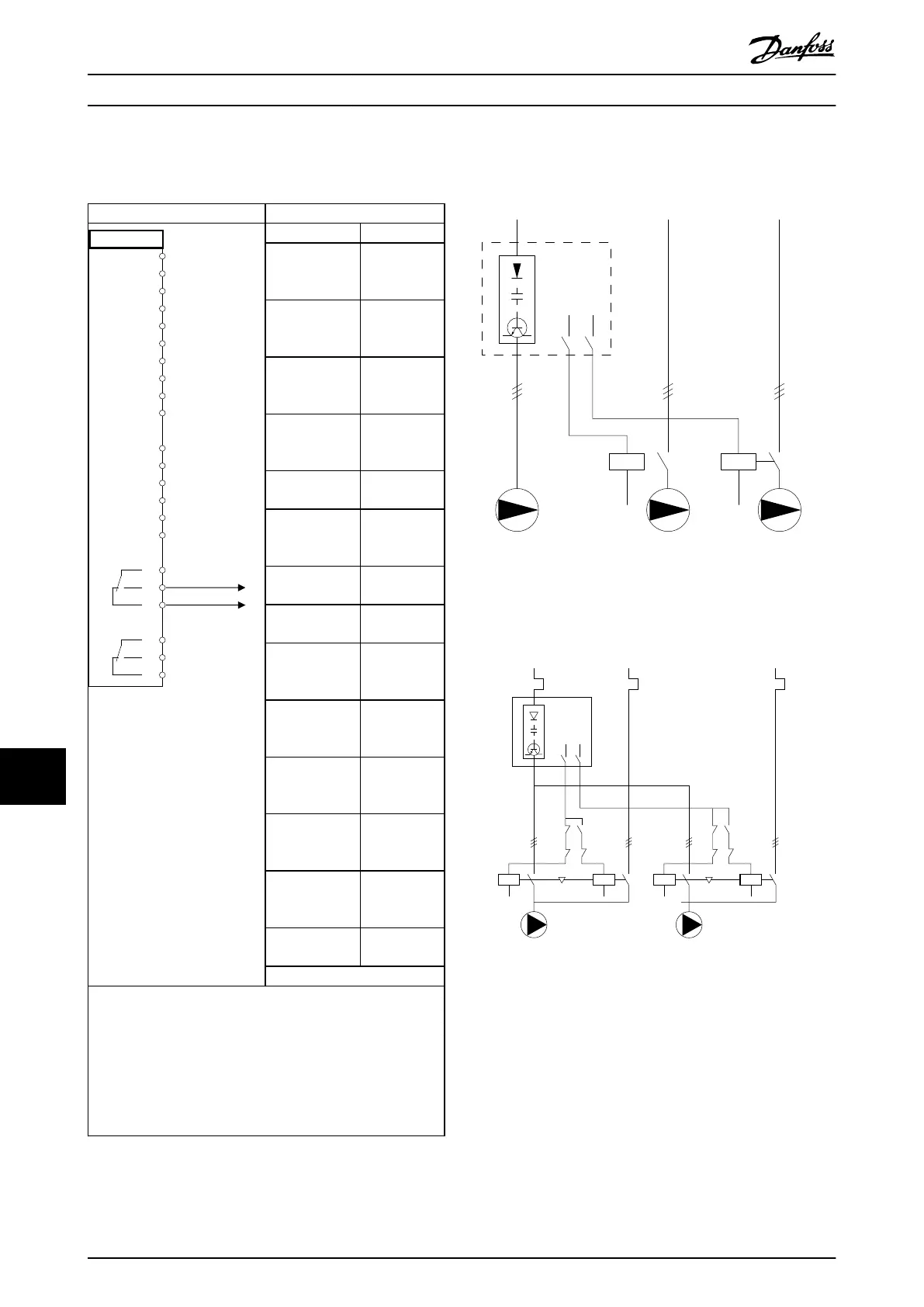
Table 12.13 Wiring Conguration for a Relay Set-up with
Smart Logic Control
12.11
Wiring Conguration for a Fixed
Variable-speed Pump
L1/L2/L3 L1/L2/L3 L1/L2/L3
Power Section
RELAY 1
RELAY 2
130BA376.10
Illustration 12.5 Fixed Variable Speed Pump Wiring Diagram
12.12 Wiring Conguration for Lead Pump
Alternation
130BA377.13
L1/L2/L3
FC
L1/L2/L3
L1/L2/L3
k3
k2
k3
k1
K2
K1
K1
K1
K4
K3
K4
K3
R1
R2
Illustration 12.6 Lead Pump Alternation Wiring Diagram.
Every pump must be connected to 2 contactors (K1/K2 and
K3/K4) with a mechanical interlock. Thermal relays or other
motor overload protection devices must be applied
according to local regulation and/or individual demands.
•
Relay 1 (R1) and relay 2 (R2) are the built-in relays
in the drive.
•
When all relays are de-energized, the 1
st
built-in
relay that is energized cuts in the contactor
corresponding to the pump controlled by the
Application Examples
VLT
®
HVAC Drive FC 102
214 Danfoss A/S © 11/2017 All rights reserved. MG16C302
1212
 Loading...


