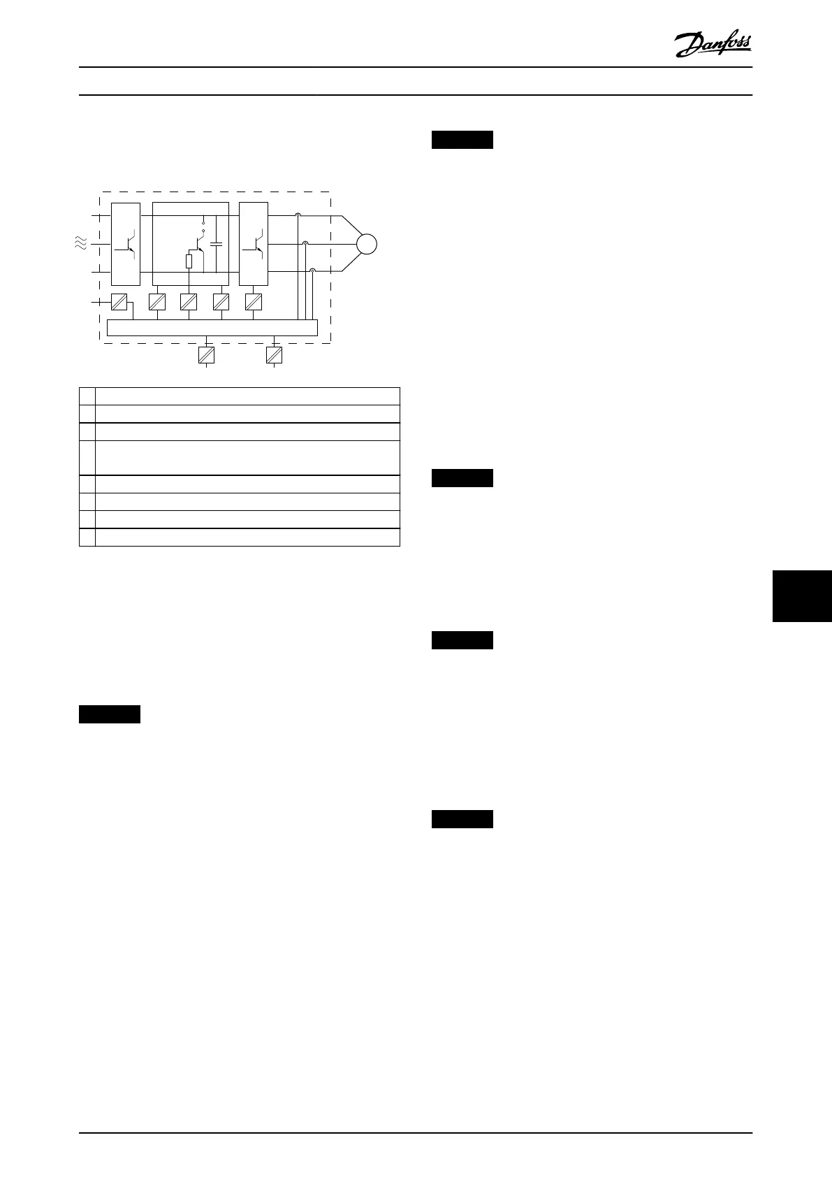
Electrical isolation is provided as shown (see
Illustration 10.27). The components described comply with
both PELV and the galvanic isolation requirements.
1 Current transducers
2 Galvanic isolation for the RS485 standard bus interface
3 Gate drive for the IGBTs
4 Supply (SMPS) including signal isolation of V DC, indicating
the intermediate current voltage
5 Galvanic isolation for the 24 V back-up option
6 Opto-coupler, brake module (optional)
7 Internal inrush, RFI, and temperature measurement circuits
8 Customer relays
Illustration 10.27 Galvanic Isolation
10.16
EMC-compliant Installation
To obtain an EMC-compliant installation, follow the
instructions provided in the operating guide. For an
example of proper EMC installation, see Illustration 10.28.
NOTICE
TWISTED SHIELD ENDS (PIGTAILS)
Twisted shield ends increase the shield impedance at
higher frequencies, which reduces the shield eect and
increases the leakage current. Avoid twisted shield ends
by using integrated shield clamps.
•
For use with relays, control cables, a signal
interface, eldbus, or brake, connect the shield to
the enclosure at both ends. If the ground path
has high impedance, is noisy, or is carrying
current, break the shield connection on 1 end to
avoid ground current loops.
•
Convey the currents back to the unit using a
metal mounting plate. Ensure good electrical
contact from the mounting plate through the
mounting screws to the drive chassis.
•
Use shielded cables for motor output cables. An
alternative is unshielded motor cables within
metal conduit.
NOTICE
SHIELDED CABLES
If shielded cables or metal conduits are not used, the
unit and the installation do not meet regulatory limits
on radio frequency (RF) emission levels.
•
Ensure that motor and brake cables are as short
as possible to reduce the interference level from
the entire system.
•
Avoid placing cables with a sensitive signal level
alongside motor and brake cables.
•
For communication and command/control lines,
follow the particular communication protocol
standards. For example, USB must use shielded
cables, but RS485/ethernet can use shielded UTP
or unshielded UTP cables.
•
Ensure that all control terminal connections are
PELV.
NOTICE
EMC INTERFERENCE
Use shielded cables for motor and control wiring. Make
sure to separate mains input, motor, and control cables
from one another. Failure to isolate these cables can
result in unintended behavior or reduced performance.
Minimum 200 mm (7.9 in) clearance between mains
input, motor, and control cables are required.
NOTICE
INSTALLATION AT HIGH ALTITUDE
There is a risk for overvoltage. Isolation between
components and critical parts could be insucient, and
not comply with PELV requirements. Reduce the risk for
overvoltage by using external protective devices or
galvanic isolation.
For installations above 2000 m (6500 ft) altitude, contact
Danfoss regarding PELV compliance.
NOTICE
PELV COMPLIANCE
Prevent electric shock by using protective extra low
voltage (PELV) electrical supply and complying with local
and national PELV regulations.
Electrical Installation Con... Design Guide
MG16C302 Danfoss A/S © 11/2017 All rights reserved. 195
10 10
 Loading...


