NOTICE
The plinth is provided in the same packaging as the frequency converter but is not attached to enclosure types F1-F4
during shipment. The plinth is required to allow airflow to the frequency converter to provide proper cooling. The F
enclosures should be positioned on top of the plinth in the final installation location. The angle from the top of the
frequency converter to the lifting cable should be 60° or greater.
In addition to the drawings above a spreader bar is an acceptable way to lift the F enclosures.
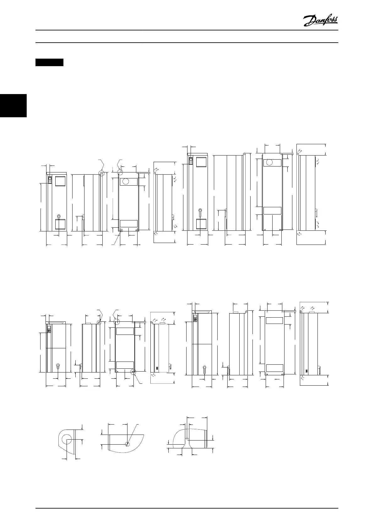
3.2.5 Mechanical Dimensions
IP21 AND IP54 / UL AND NEMA TYPE 1 AND 12
A
B
C
120
(4.7)
177.0
(7.0)
354.0
(13.9)
1166
(45.9)
310
(12.2)
163
(6.4)
420
(16.5)
981
(38.6)
74
(2.9)
417
(16.4)
380
(15.0)
D1
D2
130BA443.11
417
(16.4)
380
(15.0)
225
(8.9)
225
(8.9)
225.0
(8.9)
225.0
(8.9)
369.0
(14.5)
849
(33.4)
1209
(47.6)
160.0
(6.3)
160.0
(6.3)
160.0
(6.3)
160.0
(6.3)
304
(12.0)
304
(12.0)
25
(1.0)
25
(1.0)
1154
(45.4)
1362
(53.6)
420
(16.5)
157
(6.2)
72
(2.8)
1547
(60.9)
1589
(62.6)
423
(16.6)
120
(4.7)
1535
(60.4)
184.5
(7.3)
977
(38.5)
Illustration 3.10
*
Note airflow directions
A
B
C
IP00 / CHASSIS
IP00/IP21/IP54 - ALL SIZES
1099
43.3( )
1280
50.4( )
1327
52.2
(
)
375
14.8( )
417
16.4( )
298
11.7(
)
304
12.0(
)
120
4.7(
)
977
38.5( )
160
6.3( )
185
7.3( )
369
14.5( )
1282
50.5( )
25
1.0( )
161
6.3( )
225
(8.9)
225
(8.9)
997
39.3( )
818
32.2( )
408
16.1( )
66
2.6( )
408
16.1(
)
66
2.6( )
298
11.7
( )
375
14.8( )
1046
41.2( )
120
4.7( )
696
27.4( )
160
6.3( )
1001
25
1.0( )
39.4(
)
304
12.0( )
151
5.9( )
157
6.2( )
147
5.8( )
417
16.4( )
177
7.0( )
354
13.9( )
25
1.0( )
22
0.9
( )
49
1.9( )
25
1.0( )
Ø 11
.4( )
20.0
0.8
( )
10
0.4
( )
51
2.0( )
11
0.4( )
160.0
6.30(
)
160.0
6.30( )
225.0
8.9( )
225.0
8.9( )
D3 D4
BA
C
22
0.9
( )
138BA442.10
Illustration 3.11
How to Install VLT AQUA Drive FC 202 Operation Instructions
12 MG20P402 - Rev. 2013-12-16
33
 Loading...


