Very long control cables and analogue signals may in rare
cases and depending on installation result in 50/60 Hz
earth loops due to noise from mains supply cables.
If this occurs, it may be necessary to break the screen or
insert a 100 nF capacitor between screen and chassis.
The digital and analog inputs and outputs must be
connected separately to the frequency converter common
inputs (terminal 20, 55, 39) to avoid earth currents from
both groups to affect other groups. For example, switching
on the digital input may disturb the analog input signal.
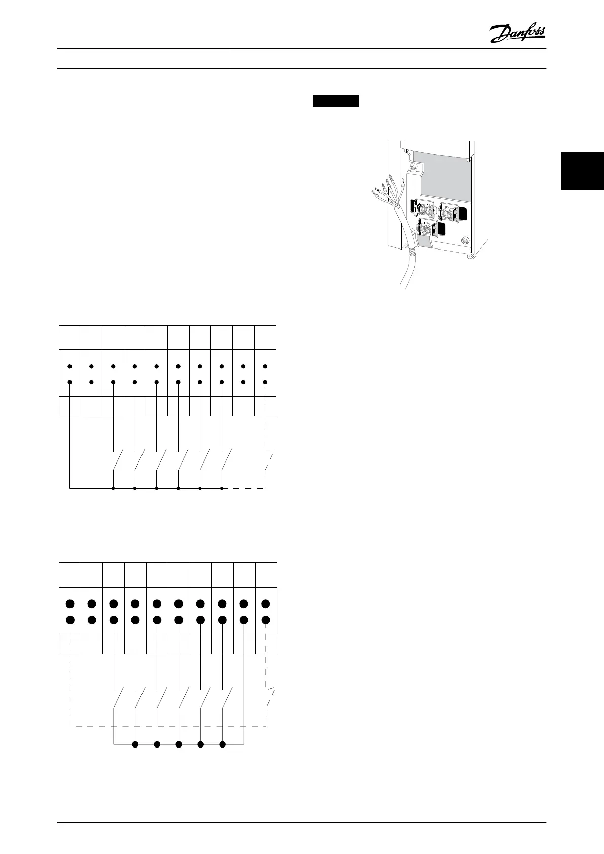
Input polarity of control terminals
12 13 18 19 27 29 32 33 20 37
+24 VDC
0 VDC
130BT106.10
PNP (Source)
Digital input wiring
Illustration 3.81
NPN (Sink)
Digital input wiring
12 13 18 19 27 29 32 33 20 37
+24 VDC
0 VDC
130BT107.11
Illustration 3.82
NOTICE
Control cables must be screened/armoured.
Illustration 3.83
Remember to connect the shields in a proper way to
ensure optimum electrical immunity.
3.6.24
Switches S201, S202, and S801
Switches S201 (A53) and S202 (A54) are used to select a
current (0-20 mA) or a voltage (-10 to +10 V) configuration
of the analog input terminals 53 and 54.
Switch S801 (BUS TER.) can be used to enable termination
on the RS-485 port (terminals 68 and 69).
See Illustration 3.79.
Default setting:
S201 (A53) = OFF (voltage input)
S202 (A54) = OFF (voltage input)
S801 (Bus termination) = OFF
How to Install VLT AQUA Drive FC 202 Operation Instructions
MG20P402 - Rev. 2013-12-16 65
3 3
 Loading...


