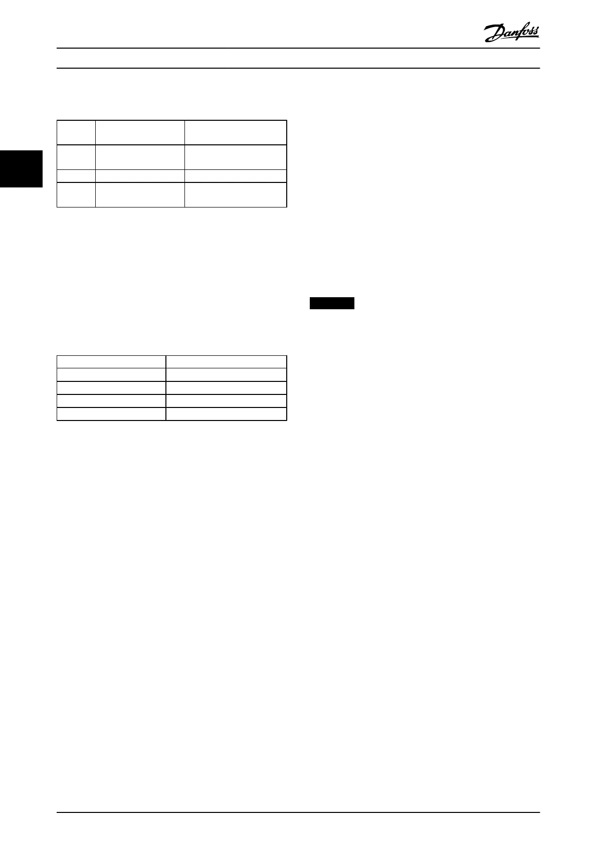
3.6.17 F Enclosure Mains Contactors
Enclosure
Type Power & Voltage Type
F3
P500-P560 380-480 V &
P710-P900 525-690 V Eaton XTCE650N22A
F3 P 630-P710 380-480 V Eaton XTCEC14P22B
F4
P800-P1M0 380-480 V &
P1M0-P1M4 525-690 V Eaton XTCEC14P22B
Table 3.46
3.6.18 Motor Insulation
For motor cable lengths ≤ the maximum cable length
listed in , the recommended motor insulation ratings are in
Table 3.47. The peak voltage can be up to twice the DC
link voltage, 2.8 times the mains voltage, due to
transmission line effects in the motor cable. If a motor has
a lower insulation rating, use a dU/dt or sine wave filter.
Nominal Mains Voltage Motor Insulation
U
N
≤ 420 V
Standard U
LL
= 1300 V
420 V < U
N
≤ 500 V Reinforced U
LL
= 1600 V
500 V < U
N
≤ 600 V Reinforced U
LL
= 1800 V
600 V < U
N
≤ 690 V Reinforced U
LL
= 2000 V
Table 3.47 Motor Insulation at Various Nominal Mains Voltages
3.6.19
Motor Bearing Currents
For motors with a rating 110 kW or higher operating via
frequency converters use NDE (Non-Drive End) insulated
bearings to eliminate circulating bearing currents due to
the physical size of the motor. To minimise DE (Drive End)
bearing and shaft currents, proper grounding of the
frequency converter, motor, driven machine, and motor to
the driven machine is required. Although failure due to
bearing currents is rare, if it occurs, use the following
mitigation strategies.
Standard mitigation strategies
•
Use an insulated bearing
•
Apply rigorous installation procedures
-
Ensure the motor and load motor are
aligned
-
Strictly follow the EMC Installation
guideline
-
Reinforce the PE so the high frequency
impedance is lower in the PE than the
input power leads
-
Provide a good high frequency
connection between the motor and the
frequency converter by screened cable,
which has a 360° connection in the
motor and frequency converter
-
Ensure that the impedance from
frequency converter to building ground
is lower than the grounding impedance
of the machine. Make a direct earth
connection between the motor and load
motor
•
Apply conductive lubrication
•
Try to ensure that the line voltage is balanced to
ground. This can be difficult for IT, TT, TN-CS or
Grounded leg systems
•
Use an insulated bearing as recommended by the
motor manufacturer
NOTICE
Motors from reputable manufacturers typically have
these fitted as standard in motors of this size.
If none of these strategies works, consult the factory.
If necessary after consulting Danfoss:
•
Lower the IGBT switching frequency
•
Modify the inverter waveform, 60° AVM vs.
SFAVM
•
Install a shaft grounding system or use an
isolating coupling between motor and load
•
Use minimum speed settings if possible
•
Use a dU/dt or sinus filter
3.6.20
Control Cable Routing
Tie down all control wires to the designated control cable
routing as shown in the picture. Remember to connect the
shields in a proper way to ensure optimum electrical
immunity.
Fieldbus connection
Connections are made to the relevant options on the
control card. For details, see the relevant fieldbus
instruction. The cable must be placed in the provided path
inside the frequency converter and tied down with other
control wires (see illustrations).
How to Install
VLT AQUA Drive FC 202 Operation Instructions
60 MG20P402 - Rev. 2013-12-16
33
 Loading...


