5 How to programme the frequency converter
5.1 How to programme
The parameters are grouped into various parameter groups for easy selection of the correct parameter for optimized
frequency converter operation.
Overview of parameter groups
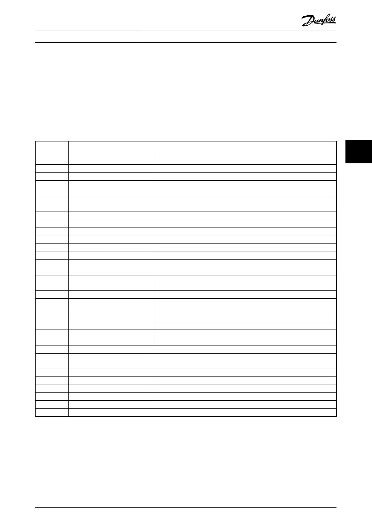
Group Title Function
0-** Operation/Display Parameters related to the fundamental functions of the frequency converter,
function of the LCP keys and configuration of the LCP display.
1-** Load/Motor Parameter group for motor settings.
2-** Brakes Parameter group for setting brake features in the frequency converter.
3-** Reference/Ramps Parameters for reference handling, definitions of limitations, and configuration of
the reaction of the frequency converter to changes.
4-** Limits/Warnings Parameter group for configuring limits and warnings.
5-** Digital In/Out Parameter group for configuring the digital inputs and outputs.
6-** Analog In/Out Parameter group for configuration of the analog inputs and outputs.
8-** Communication and Options Parameter group for configuring communications and options.
9-** Profibus Parameter group for Profibus-specific parameters (requires profibus option).
10-** DeviceNet Fieldbus Parameter group for DeviceNet-specific parameters (requires DeviceNet option).
13-** Smart Logic Parameter group for Smart Logic Control
14-** Special Functions Parameter group for configuring special frequency converter functions.
15-** Drive Information Parameter group containing frequency converter information such as operating
data, hardware configuration and software versions.
16-** Data Readouts Parameter group for data read-outs, e.g. actual references, voltages, control, alarm,
warning and status words.
18-** Info and Readouts This parameter group contains the last 10 Preventive Maintenance logs.
20-** Drive Closed Loop This parameter group is used for configuring the closed loop PID Controller that
controls the output frequency of the unit.
21-** Extended Closed Loop Parameters for configuring the three Extended Closed Loop PID Controllers.
22-** Application Functions These parameters monitor water applications.
23-** Time-based Functions These parameters are for actions needed to be performed on a daily or weekly
basis, e.g. different references for working hours/non-working hours.
24-** Application Functions 2 Parameters for the Drive Bypass.
25-** Basic Cascade Controller Functions Parameters for configuring the Basic Cascade Controller for sequence control of
multiple pumps.
26-** Analog I/0 Option MCB 109 Parameters for configuring the Analog I/0 Option MCB 109.
27-** Extended Cascade Control Parameters for configuring the Extended Cascade Control (MCO 101/MCO 102).
29-** Water Application Functions Parameters for setting water specific functions.
30-** Special Features Parameters for configuring the brake resistor value.
31-** Bypass Option Parameters for configuring the Bypass Option (MCO 104).
35-** Sensor Input Option Parameters for configuring the Sensor Input Option (MCB 114)
Table 5.1 Parameter Groups
Parameter descriptions and selections are displayed on the graphic (GLCP) or numeric (NLCP) in the display area. (See for
details.) Access the parameters by pressing the [Quick Menu] or [Main Menu] key on the control panel. The quick menu is
used primarily for commissioning the unit at start-up by providing those parameters necessary to start operation. The main
menu provides access to all parameters for detailed application programming.
How to programme the freque...
VLT AQUA Drive FC 202 Operation Instructions
MG20P402 - Rev. 2013-12-16 79
5 5
 Loading...


