5.3 Electrical Installation
5.3.1 Cables General
NOTE!
Cables General
Always comply with national and local regulations on cable cross-sections.
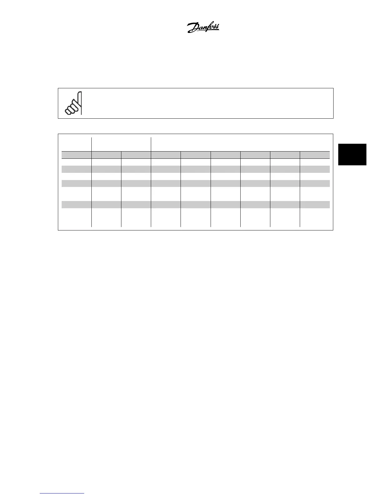
Details of terminal tightening torques.
Power (kW) Torque (Nm)
Enclosure 200-240 V 380-480 V Line Motor DC connection Brake Ground Relay
A2 0.25 - 3.0 0.37 - 4.0 1.8 1.8 1.8 1.8 3 0.6
A3 3.7 5.5 - 7.5 1.8 1.8 1.8 1.8 3 0.6
A5 0.25 - 3.7 0.37 - 7.5 1.8 1.8 1.8 1.8 3 0.6
B1 5.5 - 7.5 11 - 18 1.8 1.8 1.5 1.5 3 0.6
B2 11 - 15
22
30
2.5
4.5
2.5
4.5
3.7
3.7
3.7
3.7
3
3
0.6
0.6
C1 18 - 22 37 - 55 10 10 10 10 3 0.6
C2 30 - 45
75
90
14
24
14
24
14
14
14
14
3
3
0.6
0.6
Table 5.3: Tightening of terminals.
5.3.2 Removal of Knockouts for Extra Cables
1. Remove the cable entry from the adjustable frequency drive (this prevents foreign parts from falling into the adjustable frequency drive when
removing knockouts)
2. The cable entry must be supported around the knockout you intend to remove.
3. The knockout can now be removed with a strong mandrel and a hammer.
4. Remove burrs from the hole.
5. Mount cable entry on adjustable frequency drive.
VLT
®
AQUA Drive Design Guide 5 How to Install
MG.20.N5.22 - VLT
®
is a registered Danfoss trademark
5-15
5
 Loading...


