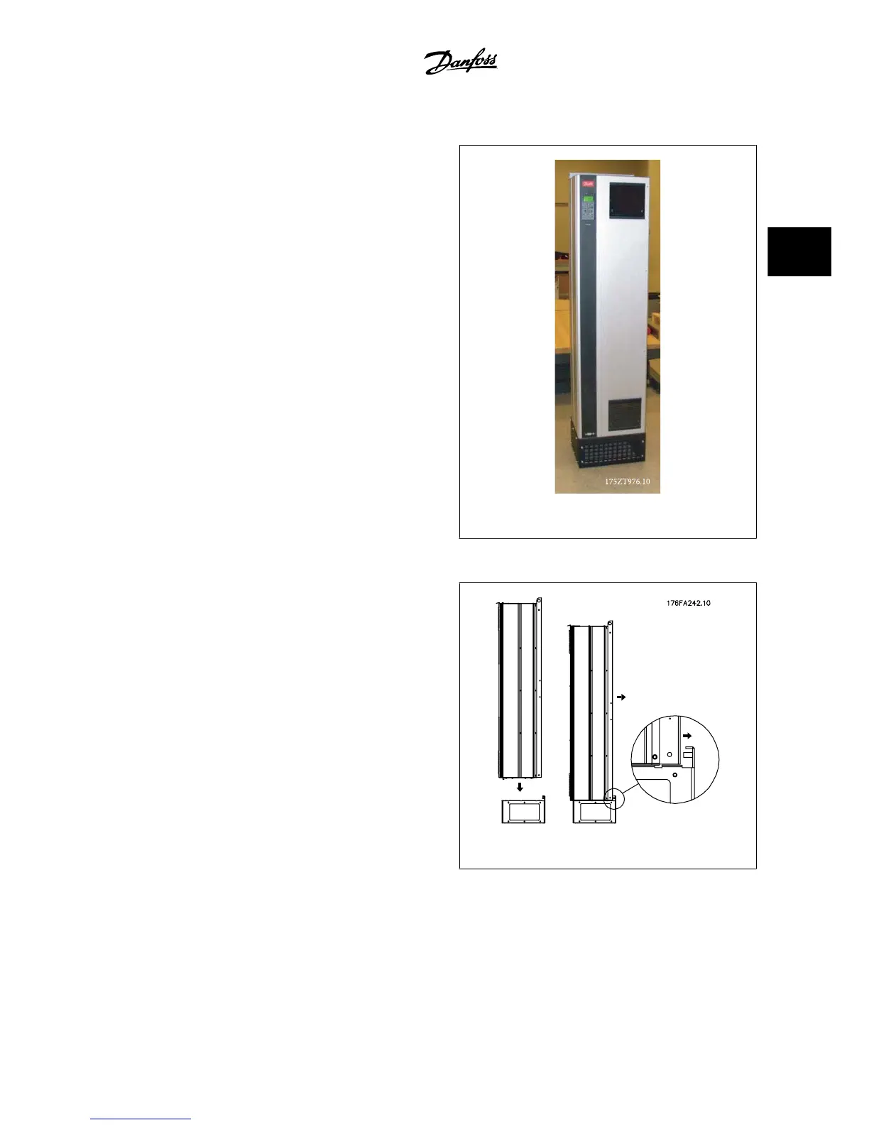
3.7.3 Installation on Pedestal
This section describes the installation of a pedestal unit available for the
adjustable frequency drives frames D1 and D2. This is an 8 in [200 mm]
high pedestal that allows these frames to be floor mounted. The front of
the pedestal has openings for input air to the power components.
The adjustable frequency drive connector plate must be installed to pro-
vide adequate cooling air to the control components of the adjustable
frequency drive via the door fan and to maintain the IP21/NEMA 1 or
IP54/NEMA 12 degrees of enclosure protections.
Figure 3.32: Drive on pedestal
There is one pedestal that fits both frames D1 and D2. Its ordering number is 176F1827. The pedestal is standard for E1 frame.
Required Tools:
• Socket wrench with 0.28–0.67 in [7–17 mm] sockets
• T30 Torx Driver
Torques:
• M6 - 4.0 Nm (35 in-lbs)
• M8 - 9.8 Nm (85 in-lbs)
• M10 - 19.6 Nm (170 in-lbs)
Kit Contents:
•Pedestal parts
• Instruction Manual
Figure 3.33: Mount the drive onto pedestal.
VLT
®
AQUA Drive Design Guide 3 VLT AQUA Selection
MG.20.N5.22 - VLT
®
is a registered Danfoss trademark
3-51
3
 Loading...


