Stop the AMA during operation
1. Press the [OFF] key. The adjustable frequency drive enters into alarm mode and the display shows that the AMA was terminated by the user.
Successful AMA
1. The display shows “Press [OK] to finish AMA”.
2. Press the [OK] key to exit the AMA state.
Unsuccessful AMA
1. The adjustable frequency drive enters into alarm mode. A description of the alarm can be found in the
Troubleshooting
section.
2. "Report Value” in the [Alarm Log] shows the last measuring sequence carried out by the AMA before the adjustable frequency drive entered
alarm mode. This number along with the description of the alarm will assist you in troubleshooting. If you contact Danfoss Service, make sure
to mention number and alarm description.
NOTE!
Unsuccessful AMA is often caused by incorrectly registered motor nameplate data or a difference between the motor power size and
the VLT AQUA Drive power size that is too great.
Step 4. Set speed limit and ramp time.
Set up the desired limits for speed and ramp time.
Minimum Reference par. 3-02
Maximum Reference par. 3-03
Motor Speed Low Limit par. 4-11 or 4-12
Motor Speed High Limit par. 4-13 or 4-14
Ramp-up Time 1 [s] par. 3-41
Ramp-down Time 1 [s] par. 3-42
5.7.1 Safe Stop Installation
To carry out an installation of a Category 0 Stop (EN60204) in
conformance with Safety Category 3 (EN954-1), follow these
instructions:
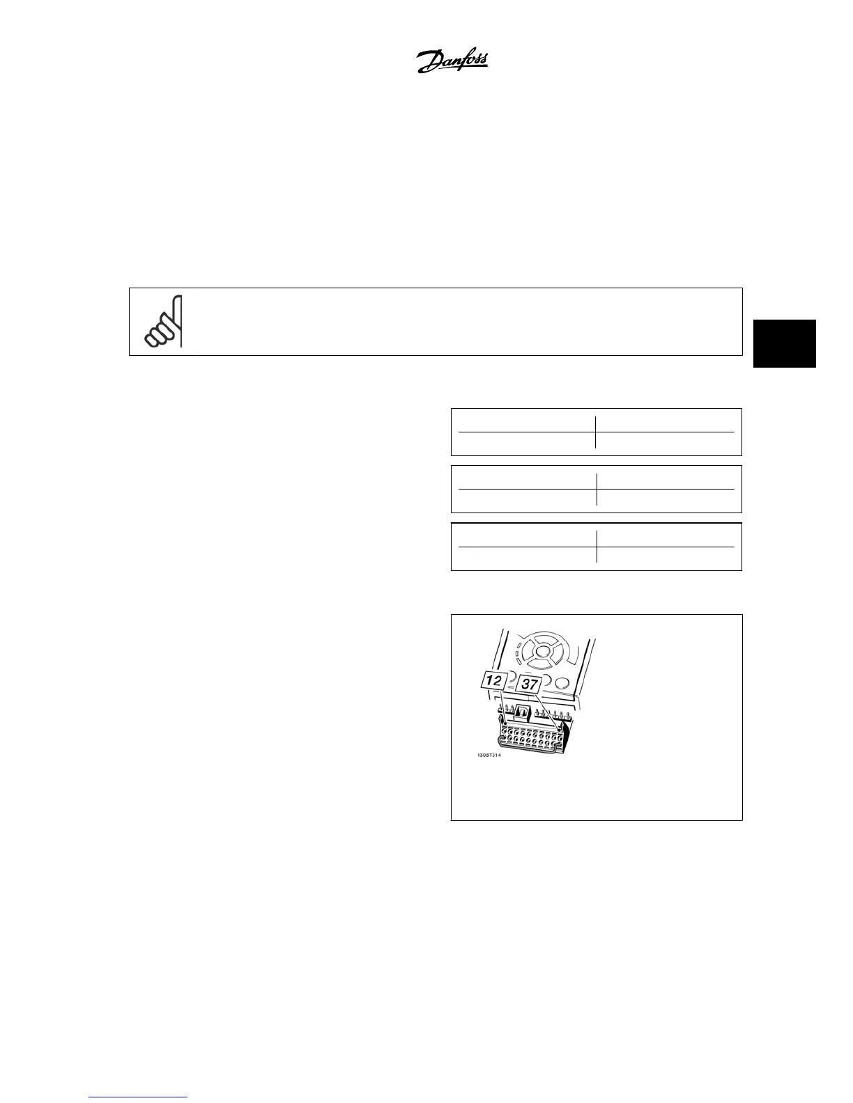
1. The bridge (jumper) between Terminal 37 and 24 V DC of the
FC 202 must be removed. Cutting or breaking the jumper is not
sufficient. Remove it entirely to avoid short-circuiting. See jump-
er on illustration.
2. Connect terminal 37 to 24 V DC by a short circuit-protected ca-
ble. The 24 V DC voltage supply must be interruptible by an
EN954-1 category 3 circuit interrupt device. If the interrupt de-
vice and the adjustable frequency drive are placed in the same
installation panel, you can use a regular cable instead of a pro-
tected one.
Figure 5.37: Bridge jumper between terminal 37 and 24
VDC.
The illustration below shows a Stopping Category 0 (EN 60204-1) with safety Cat. 3 (EN 954-1). The circuit interrupt is caused by an opening door contact.
The illustration also shows how to connect a non-safety-related hardware coast.
VLT
®
AQUA Drive Design Guide 5 How to Install
MG.20.N5.22 - VLT
®
is a registered Danfoss trademark
5-47
5
 Loading...


