5.8 Additional Connections
5.8.1 Relay Output
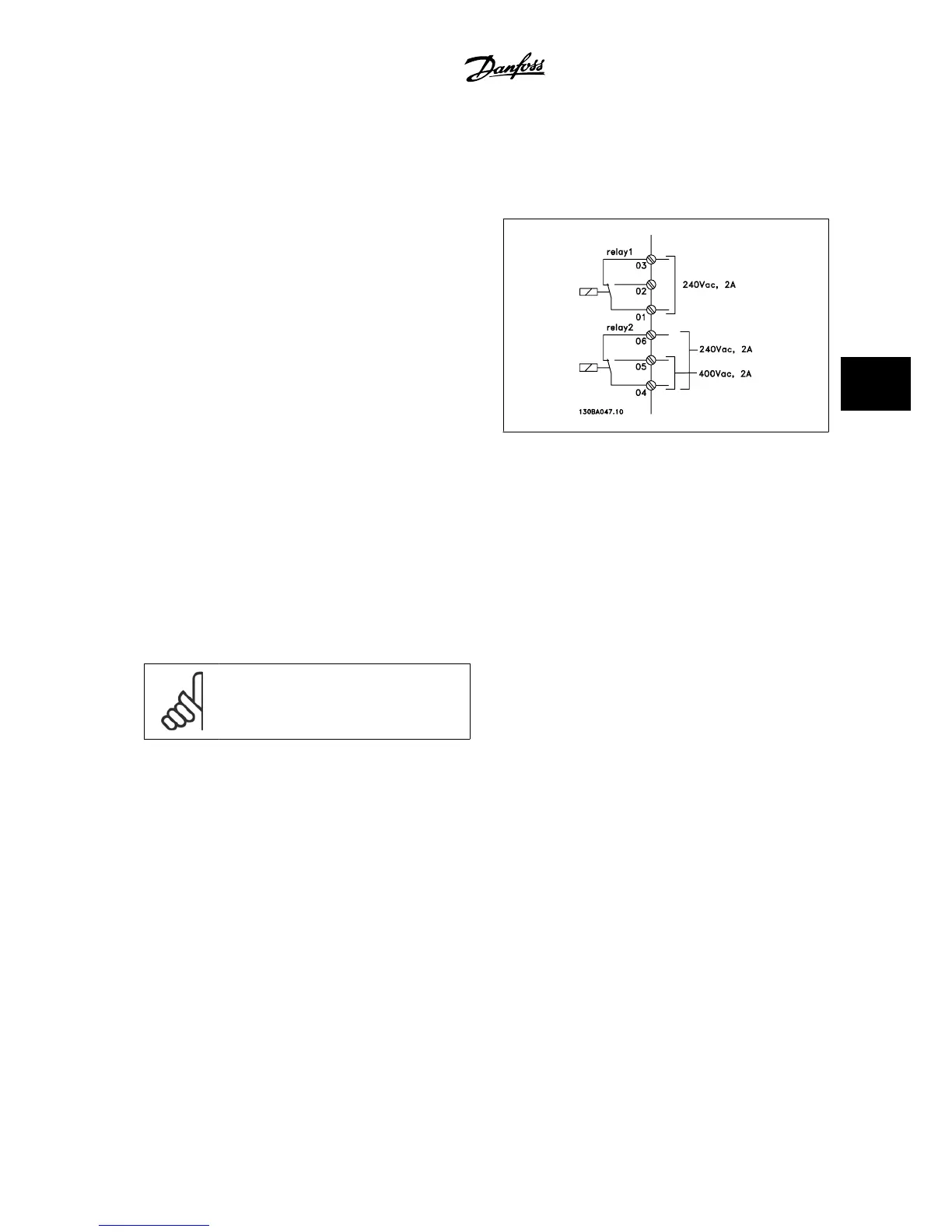
Relay 1
• Terminal 01: common
• Terminal 02: normal open 240 V AC
• Terminal 03: normal closed 240 V AC
Relay 2
• Terminal 04: common
• Terminal 05: normal open 400 V AC
• Terminal 06: normal closed 240 V AC
Relay 1 and relay 2 are programmed in par. 5-40
Function Relay
,
par. 5-41
On Delay, Relay
, and par. 5-42
Off Delay, Relay
.
Additional relay outputs by using option module MCB 105.
5.8.2 Parallel Connection of Motors
The adjustable frequency drive can control several parallel-connected
motors. The total current consumption of the motors must not exceed
the rated output current I
INV
for the adjustable frequency drive.
NOTE!
When motors are connected in parallel, par. 1-29
Au-
tomatic Motor Adaptation (AMA)
cannot be used.
Problems may arise at start and at low RPM values if motor sizes are
widely different because small motors' relatively high ohmic resistance in
the stator calls for a higher voltage at start and at low RPM values.
The electronic thermal relay (ETR) of the adjustable frequency drive can-
not be used as motor protection for the individual motor of systems with
parallel-connected motors. Provide further motor protection with, for ex-
ample, thermistors in each motor or individual thermal relays (circuit
breakers are not a suitable means of protection).
VLT
®
AQUA Drive Design Guide 5 How to Install
MG.20.N5.22 - VLT
®
is a registered Danfoss trademark
5-49
5
 Loading...


