3.7 High Power Options
3.7.1 Installation of Duct Cooling Kit in Rittal Enclosures
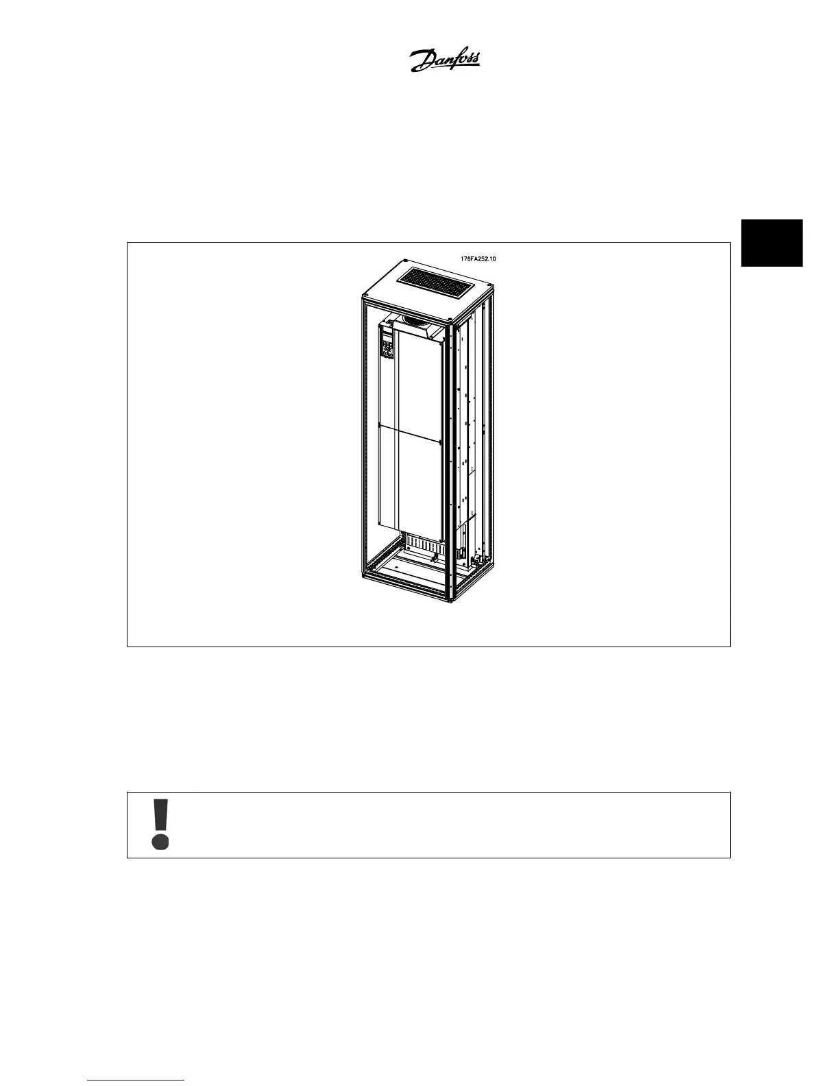
This section deals with the installation of IP00 / chassis enclosed adjustable frequency drives with duct work cooling kits in Rittal enclosures. In addition
to the enclosure an 8 in [200 mm] base/plinth is required.
Figure 3.28: Installation of IP00 in Rittal TS8 enclosure.
The minimum enclosure dimension is:
• D3 and D4 frame: Depth 19.7 in [500 mm] and width 23.6 in [600 mm].
• E2 frame: Depth 23.6 in [600 mm] and width 31.5 in [800 mm].
The maximum depth and width are as required for the installation. When using multiple adjustable frequency drives in one enclosure it is recommended
that each drive is mounted on its own back panel and supported along the mid-section of the panel. These duct work kits do not support the “in frame”
mounting of the panel (see Rittal TS8 catalog for details). The duct work cooling kits listed in the table below are suitable for use only with IP 00 / Chassis
adjustable frequency drives in Rittal TS8 IP 20 and UL and NEMA 1 and IP 54 and UL and NEMA 12 enclosures.
For the E2 frames, it is important to mount the plate at the absolute rear of the Rittal enclosure due to the weight of the adjustable
frequency drive.
VLT
®
AQUA Drive Design Guide 3 VLT AQUA Selection
MG.20.N5.22 - VLT
®
is a registered Danfoss trademark
3-47
3
 Loading...


