7.3 Network Configuration
7.3.1 VLT AQUA Adjustable Frequency Drive Set-up
Set the following parameters to enable the FC protocol for the VLT AQUA.
Parameter Number Parameter name Setting
8-30 Protocol FC
8-31 Address 1 - 126
8-32 Baud Rate 2400 - 115200
8-33 Parity/Stop bits Even parity, 1 stop bit (default)
7.4 FC Protocol Message Framing Structure
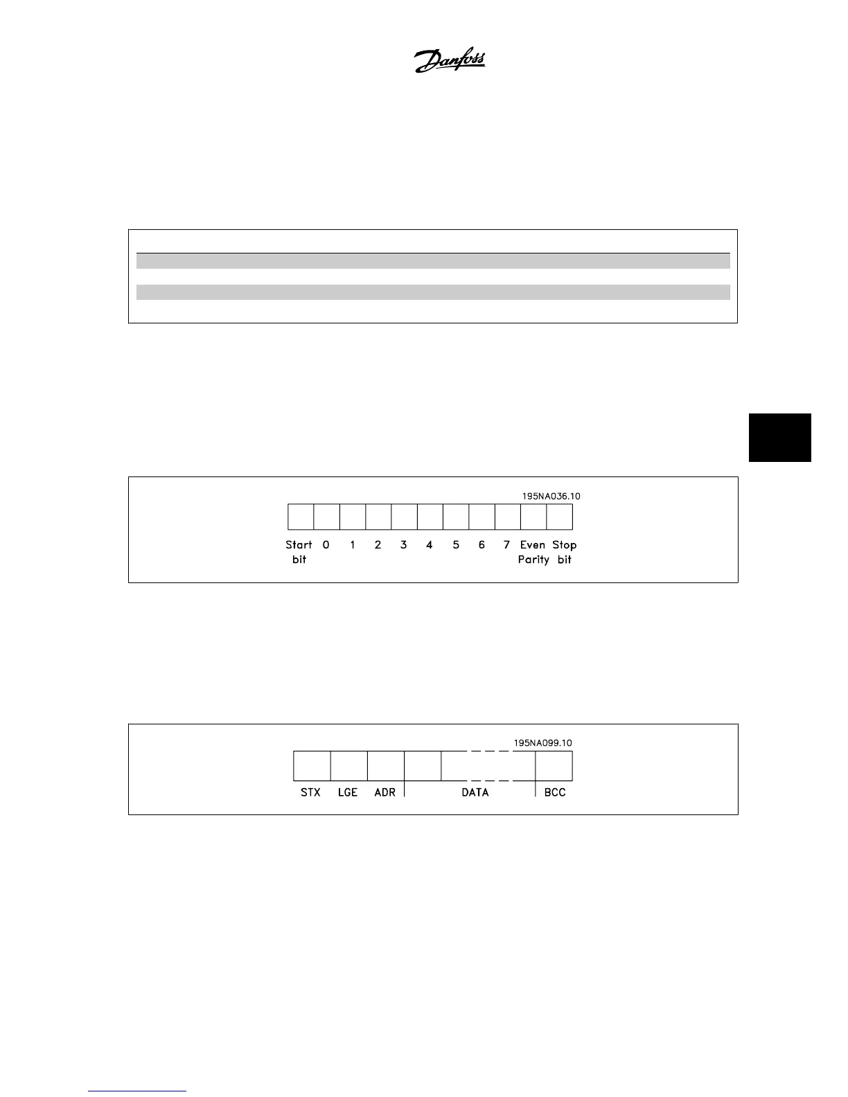
7.4.1 Content of a Character (byte)
Each character transferred begins with a start bit. Then 8 data bits are transferred, corresponding to a byte. Each character is secured via a parity bit,
which is set at "1" when it reaches parity (i.e., when there is an equal number of 1’s in the 8 data bits and the parity bit in total). A character is completed
by a stop bit, thus consisting of 11 bits in all.
7.4.2 Message Structure
Each message begins with a start character (STX)=02 Hex, followed by a byte denoting the message length (LGE) and a byte denoting the adjustable
frequency drive address (ADR). A number of data bytes (variable, depending on the type of message) follows. The message is completed by a data
control byte (BCC).
VLT
®
AQUA Drive Design Guide 7 RS-485 Installation and Set-up
MG.20.N5.22 - VLT
®
is a registered Danfoss trademark
7-5
7
 Loading...


