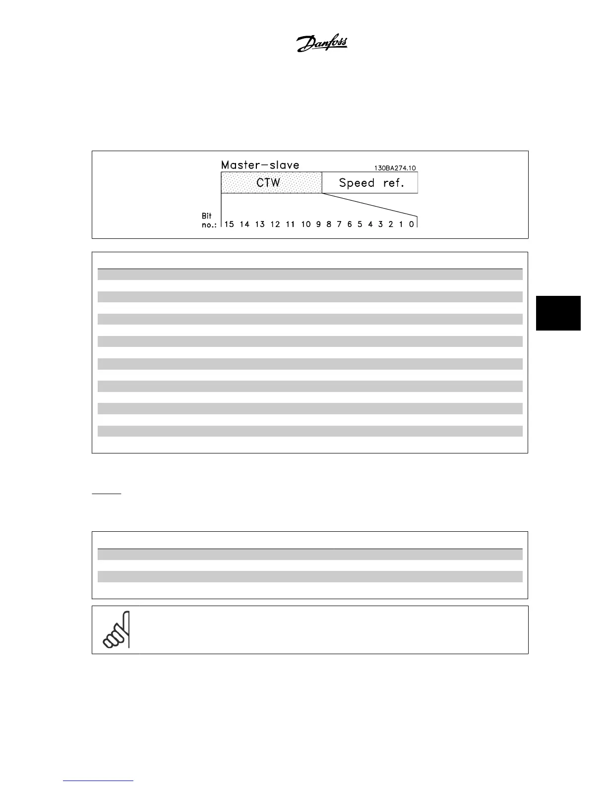
7.11 Danfoss FC Control Profile
7.11.1 Control Word According to Adjustable Frequency Drive Profile(par. 8-10
Control Pro-
file
= Adjustable Frequency profile)
Bit Bit value = 0 Bit value = 1
00 Reference value external selection lsb
01 Reference value external selection msb
02 DC brake Ramp
03 Coasting No coasting
04 Quick stop Ramp
05 Hold output frequency use ramp
06 Ramp stop Start
07 No function Reset
08 No function Jog
09 Ramp 1 Ramp 2
10 Data invalid Data valid
11 No function Relay 01 active
12 No function Relay 02 active
13 Parameter set-up selection lsb
14 Parameter set-up selection msb
15 No function Reverse
Explanation of the Control Bits
Bits 00/01
Bits 00 and 01 are used to choose between the four reference values, which are pre-programmed in par. 3-10
Preset Reference
according to the following
table:
Programmed ref. value Par. Bit 01 Bit 00
1 par. 3-10
Preset Reference
[0] 0 0
2 par. 3-10
Preset Reference
[1] 0 1
3 par. 3-10
Preset Reference
[2] 1 0
4 par. 3-10
Preset Reference
[3] 1 1
NOTE!
Make a selection in par. 8-56
Preset Reference Select
to define how Bit 00/01 gates with the corresponding function on the digital
inputs.
VLT
®
AQUA Drive Design Guide 7 RS-485 Installation and Set-up
MG.20.N5.22 - VLT
®
is a registered Danfoss trademark
7-25
7
 Loading...


