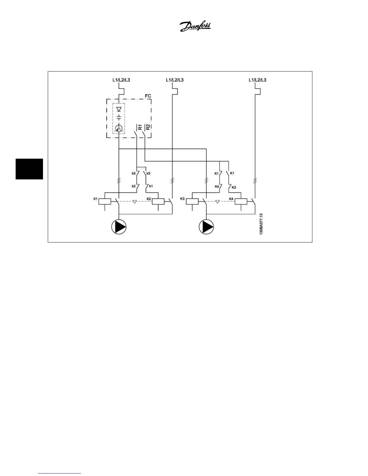
6.1.12 Lead Pump Alternation Wiring Diagram
Every pump must be connected to two contactors (K1/K2 and K3/K4) with a mechanical interlock. Thermal relays or other motor protection devices must
be applied according to local regulation and/or individual demands.
• RELAY 1 (R1) and RELAY 2 (R2) are the built-in relays in the adjustable frequency drive.
• When all relays are de-energized, the first built-in relay to be energized will cut in the contactor corresponding to the pump controlled by the
relay. For example, RELAY 1 cuts in contactor K1, which becomes the lead pump.
• K1 blocks K2 via the mechanical interlock, preventing line power to be connected to the output of the adjustable frequency drive (via K1).
• Auxiliary break contact on K1 prevents K3 from cutting in.
• RELAY 2 controls contactor K4 for on/off control of the fixed speed pump.
• At alternation, both relays de-energize, and RELAY 2 will be energized as the first relay.
6 Application Examples VLT
®
AQUA Drive Design Guide
6-8
MG.20.N5.22 - VLT
®
is a registered Danfoss trademark
6
 Loading...


