Programming Guide | VLT® AutomationDrive FC 360
Data type: Uint32 Change during operation: True
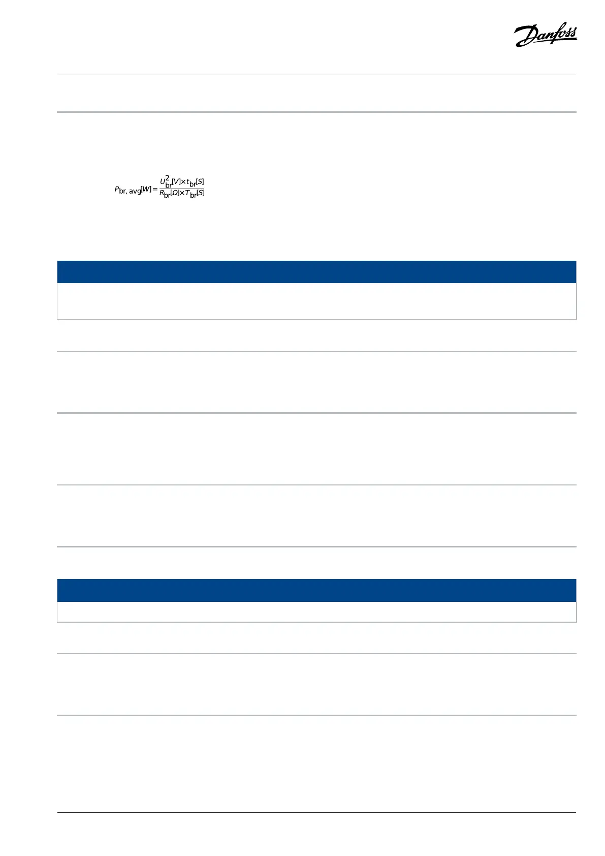
Parameter 2-12 Brake Power Limit (kW)is the expected average power dissipated in the brake resistor over a period of 120 s. It is used as
the monitoring limit for parameter 16-33 Brake Energy Average and specifies when a warning/alarm is given. To calculate parameter 2-12
Brake Power Limit (kW), the following formula can be used.
P
br,avg
is the average power dissipated in the brake resistor. R
br
is the resistance of the brake resistor. t
br
is the active breaking time within
the 120 s period T
br
. U
br
is the DC voltage where the brake resistor is active. For T4 units, the DC voltage is 770 V, which can be reduced by
parameter 2-14 Brake voltage reduce.
NOTICE
If R
br
is not known or if T
br
is different from 120 s, the practical approach is to run the brake application, read out parameter 16-33
Brake Energy Average, and then enter this value + 20% in parameter 2-12 Brake Power Limit (kW).
2-14 Brake Voltage Reduce
Default value: 0 V Parameter type: Range (0–500 V)
Setup: All setups Conversion index: 0
Data type: Uint16 Change during operation: True
Setting this parameter may change the brake resistor (parameter 2-11 Brake Resistor (ohm)).
This parameter can reduce the DC voltage where the brake resistor is active.
2-16 AC Brake, Max Current
Default value: 100% Parameter type: Range (0–160%)
Setup: All setups Conversion index: 0
Data type: Uint16 Change during operation: True
Enter the maximum allowed current when using AC brake to avoid overheating of motor windings.
NOTICE
Parameter 2-16 AC Brake, Max Current is only available for asynchronous motors.
2-17 Over-voltage Control
Default value: [0] Disabled Parameter type: Option
Setup: All setups Conversion index: –
Data type: Uint8 Change during operation: True
Overvoltage control (OVC) reduces the risk of the drive tripping due to an overvoltage on the DC link caused by generative power from
the load.
Danfoss A/S © 2024.01 AU275649936274en-001401 / 130R0507 | 81
 Loading...


