4-41 Warning Freq. High
Range: Function:
Size
related*
[ par. 4-40 -
par. 4-14 Hz]
Use this parameter to set a high
limit for the frequency range. When
the motor speed is above this limit,
the display reads SPEED HIGH. The
LCP warning light is not turned on
when this parameter set limit is
reached. Warning bit 9 is set in
parameter 16-94 Ext. Status Word.
The output relay or the digital
output can be congured to
indicate this warning.
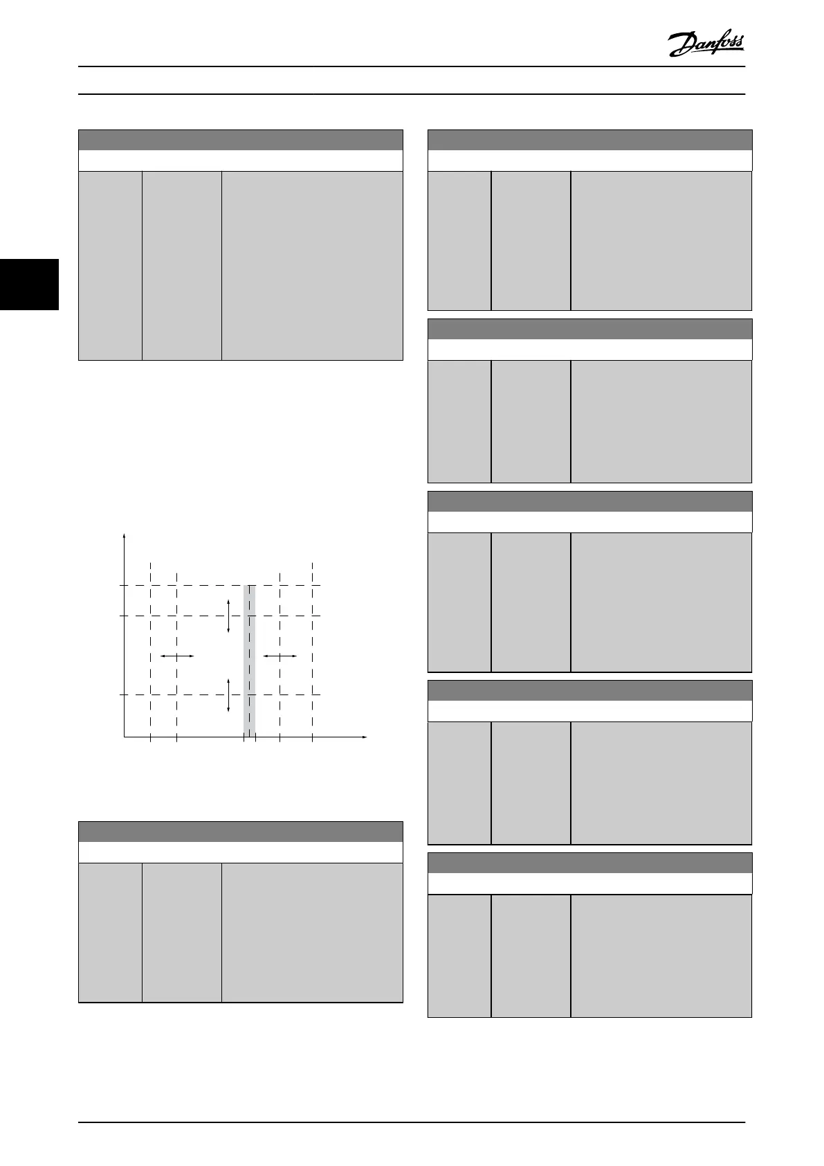
4.5.5 4-5* Adjustable Warnings
Use these parameters to adjust warning limits for current,
speed, reference, and feedback.
Warnings are shown on the LCP and can be programmed
to be outputs or to be read out via eldbus in the
extended status word.
130BA064.10
(P 4-18)
(P 4-51)
(P 4-50)
(P 4-11) (P 4-53)(P 4-52) (P 4-13)
I
HIGH
I
LOW
n
LOW
n
HIGH
n
motor
I
motor
REF
ON REF
IN RANGE
I
LIM
n
MAX
n
MIN
[RPM]
Illustration 4.25 Adjustable Warnings
4-50 Warning Current Low
Range: Function:
0 A* [ 0 - par. 4-51
A]
Enter the I
LOW
value. When the
motor current falls below this limit,
the display reads Current Low. The
signal outputs can be programmed
to produce a status signal on
terminal 27 or 29 and on relay
output 01 or 02. Refer to
Illustration 4.25.
4-51 Warning Current High
Range: Function:
Size
related*
[ par. 4-50 -
par. 16-37 A]
Enter the I
HIGH
value. When the
motor current exceeds this limit,
the display reads Current High. The
signal outputs can be programmed
to produce a status signal on
terminal 27 or 29 and on relay
output 01 or 02. Refer to
Illustration 4.25.
4-52 Warning Speed Low
Range: Function:
Size
related*
[ 0 - par. 4-53
RPM]
Enter the n
LOW
value. When the
motor speed exceeds this limit, the
display reads Speed low. The signal
outputs can be programmed to
produce a status signal on terminal
27 or 29 and on relay output 01 or
02.
4-53 Warning Speed High
Range: Function:
Size
related*
[ par. 4-52 -
60000 RPM]
Enter the n
HIGH
value. When the
motor speed exceeds this value, the
display reads Speed high. The signal
outputs can be programmed to
produce a status signal on
terminals 27 or 29 and on relay
outputs 01 or 02. Refer to
Illustration 4.25.
4-54 Warning Reference Low
Range: Function:
-999999.99
9*
[ -999999.999
- par. 4-55 ]
Enter the lower reference limit.
When the actual reference drops
below this limit, the display
indicates Ref
LOW
. The signal outputs
can be programmed to produce a
status signal on terminal 27 or 29
and on relay output 01 or 02.
4-55 Warning Reference High
Range: Function:
999999.999
*
[ par. 4-54 -
999999.999 ]
Enter the upper reference limit.
When the actual reference exceeds
this limit, the display reads Ref
high
.
The signal outputs can be
programmed to produce a status
signal on terminal 27 or 29 and on
relay output 01 or 02.
Parameter Descriptions VLT® AutomationDrive FC 361
64 Danfoss A/S © 03/2019 All rights reserved. MG06J202
44
 Loading...


