•
•
•
•
•
•
1.
-
-
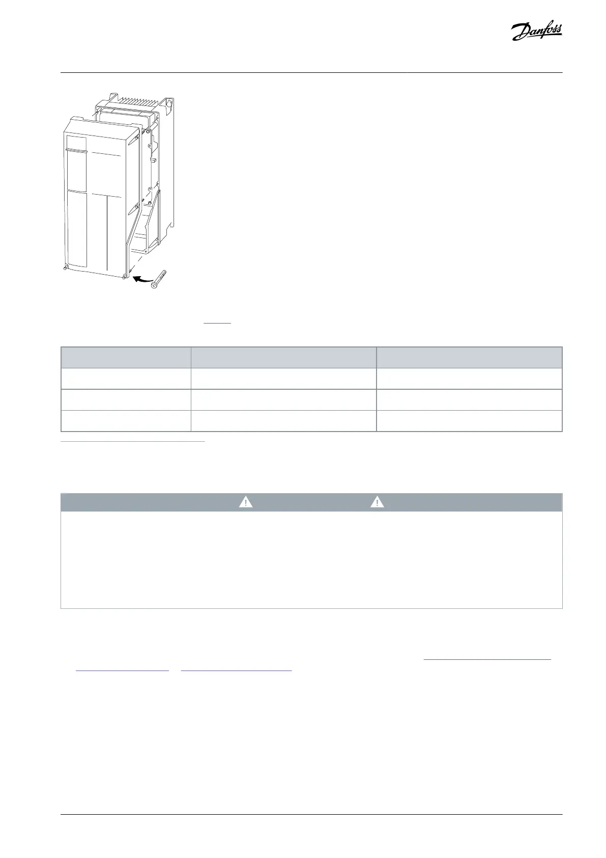
Illustration 11: Access to Wiring for IP55 and IP66 Enclosures
Before tightening the screws, refer to Table 5.
Table 5: Tightening Torques for Covers
1
No screws to tighten for A2/A3/B3/B4/C3/C4.
4.6 Connecting the Motor
W A R N I N G
INDUCED VOLTAGE
Induced voltage from output motor cables that run together can charge equipment capacitors, even with the equipment turned
off and locked out/tagged out. Failure to run output motor cables separately, or to use shielded cables, could result in death or
serious injury.
Run output motor cables separately or use shielded cables.
Simultaneously lock out/tag out all the drives.
Run output separately or
Use shielded cables.
Comply with local and national electrical codes for cable sizes. For maximum wire sizes, see 8.1 Electrical Data, 200–240 V and
3x115Y/200–139Y/240 V to 8.4 Electrical Data, 525–690 V.
Follow motor manufacturer wiring requirements.
Motor wiring knockouts or access panels are provided at the base of IP21 (NEMA 1/12) and higher units.
Do not wire a starting or pole-changing device (for example a Dahlander motor or slip ring asynchronous motor) between the
drive and the motor.
4.6.1 Grounding the Cable Shield
Procedure
Strip a section of the outer cable insulation.
AQ267037536117en-000101 / 130R0083 | 25Danfoss A/S © 2023.09
Electrical Installation
VLT HVAC Drive FC 102
Operating Guide
 Loading...


