When using a contactor with a DC coil inside in combination with STO, it is important to make a return way for the current from the
coil when turning it off. This can be done by using a freewheel diode (or, alternatively, a 30 V or 50 V MOV for quicker response time)
across the coil. Typical contactors can be bought with this diode.
8.9.3 Analog Inputs
Switch S201 and switch S202
Switch S201/switch S202 = OFF (U)
-10 V to +10 V (scaleable)
Switch S201/S202 = ON (I)
Resolution for analog inputs
Accuracy of analog inputs
Maximum error 0.5% of full scale
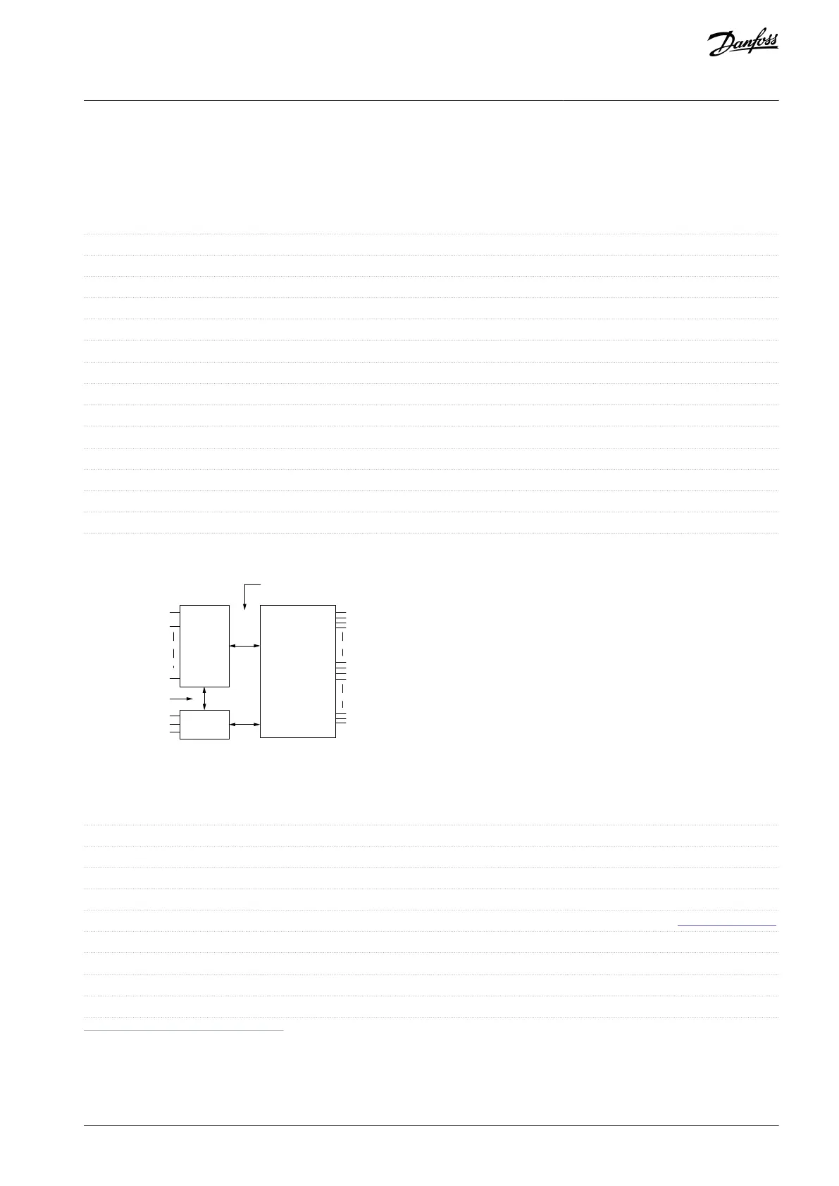
The analog inputs are galvanically isolated from the supply voltage (PELV) and other high-voltage terminals.
Functional
isolation
PELV isolation
Motor
DC-bus
High
voltage
+24 V
RS485
18
37
e30ba117.11
Illustration 33: PELV Isolation
8.9.4 Pulse/Encoder Inputs
Maximum frequency at terminals 29, 33
110 kHz (Push-pull driven)
Maximum frequency at terminals 29, 33
Maximum frequency at terminals 29, 33
See 8.9.1 Digital Inputs.
Pulse input accuracy (0.1–1 kHz)
Maximum error: 0.1% of full scale
Encoder input accuracy (1–11 kHz)
Maximum error: 0.05% of full scale
1
Pulse inputs are 29 and 33.
The pulse and encoder inputs (terminals 29 and 33) are galvanically isolated from the supply voltage (PELV) and other high-voltage
terminals.
AQ267037536117en-000101 / 130R0083 | 99Danfoss A/S © 2023.09
Specifications
VLT HVAC Drive FC 102
Operating Guide
 Loading...


