•
•
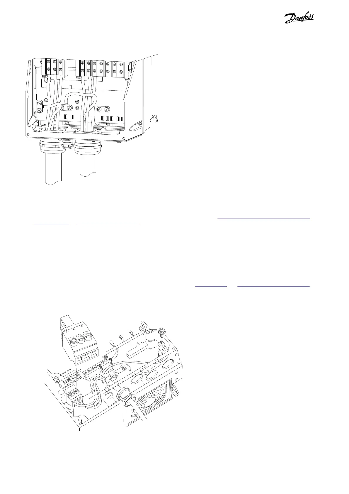
1.
2.
3.
4.
Illustration 19: Motor, Mains, and Ground Wiring for Enclosure Types B and C Using Conduit
4.7 Connecting AC Mains
Size the wiring based on the input current of the drive. For maximum wire sizes, see 8.1 Electrical Data, 200–240 V and 3x115Y/
200–139Y/240 V to 8.4 Electrical Data, 525–690 V.
Comply with local and national electrical codes for cable sizes.
4.7.1 Connecting the Drive to Mains
Procedure
Connect the 3-phase AC input power wiring to terminals L1, L2, and L3.
Depending on the configuration of the equipment, connect the input power to the mains input terminals or the input dis-
connect.
Ground the cable in accordance with the grounding instructions, see 4.3 Grounding and 4.6.1 Grounding the Cable Shield.
When supplied from an isolated mains source (IT mains or floating delta) or TT/TN-S mains with a grounded leg (grounded
delta), ensure that parameter 14-50 RFI Filter is set to [0] Off. This setting prevents damage to the DC link and reduces
ground capacity currents in accordance with IEC 61800-3.
Illustration 20: Connecting to AC Mains
AQ267037536117en-000101 / 130R008330 | Danfoss A/S © 2023.09
Electrical Installation
VLT HVAC Drive FC 102
Operating Guide
 Loading...


