EasyManuals Logo
Home>Danfoss>DC Drives>vlt FC 102

Danfoss vlt FC 102 Operating Guide

Danfoss vlt FC 102
120 pages
To Next Page IconTo Next Page
To Previous Page IconTo Previous Page
Page #8 background imageLoading...
Page #8 background image
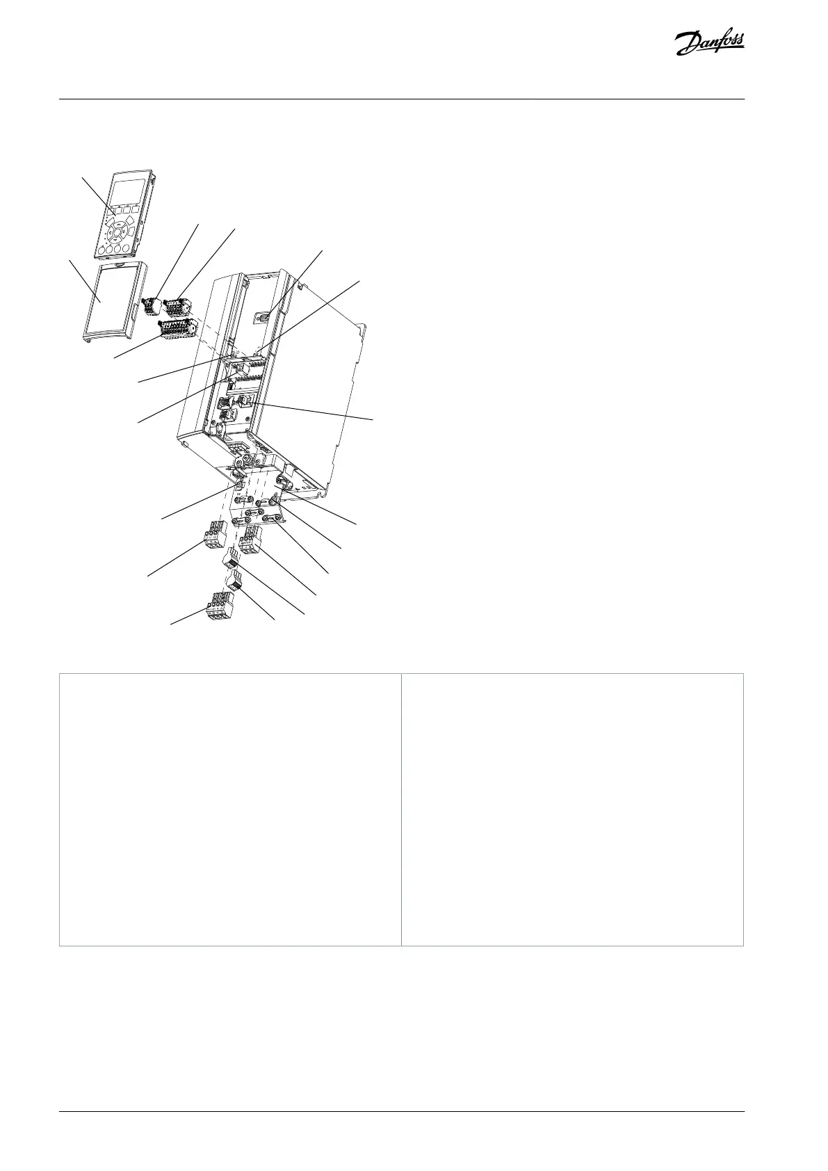
1.3.2 Exploded Views
1
2
3
4
5
6
10
11
12
13
14
8
15
16
17
18
e30bb492.12
Illustration 1: Exploded View Enclosure Type A, IP20
1
Local control panel (LCP)
2
RS485 serial bus connector (+68, -69)
3
Analog I/O connector
4
LCP input plug
5
Analog switches (A53), (A54)
6
Cable shield connector
7
Decoupling plate
8
Grounding clamp (PE)
9
Shielded cable grounding clamp and strain relief
10
Motor output terminals 96 (U), 97 (V), 98 (W)
11
Relay 2 (01, 02, 03)
12
Relay 1 (04, 05, 06)
13
Brake (-81, +82) and load sharing (-88, +89) termi-
nals
14
Mains input terminals 91 (L1), 92 (L2), 93 (L3)
15
USB connector
16
Serial bus terminal switch
17
Digital I/O and 24 V power supply
18
Cover
AQ267037536117en-000101 / 130R00838 | Danfoss A/S © 2023.09
Introduction
VLT HVAC Drive FC 102
Operating Guide

Table of Contents

Other manuals for Danfoss vlt FC 102

Questions and Answers:

Question and Answer IconNeed help?

Do you have a question about the Danfoss vlt FC 102 and is the answer not in the manual?

Danfoss vlt FC 102 Specifications

General IconGeneral
BrandDanfoss
Modelvlt FC 102
CategoryDC Drives
LanguageEnglish

Related product manuals