•
•
0.0Hz 0.000kW 0.00A
0.0Hz
0
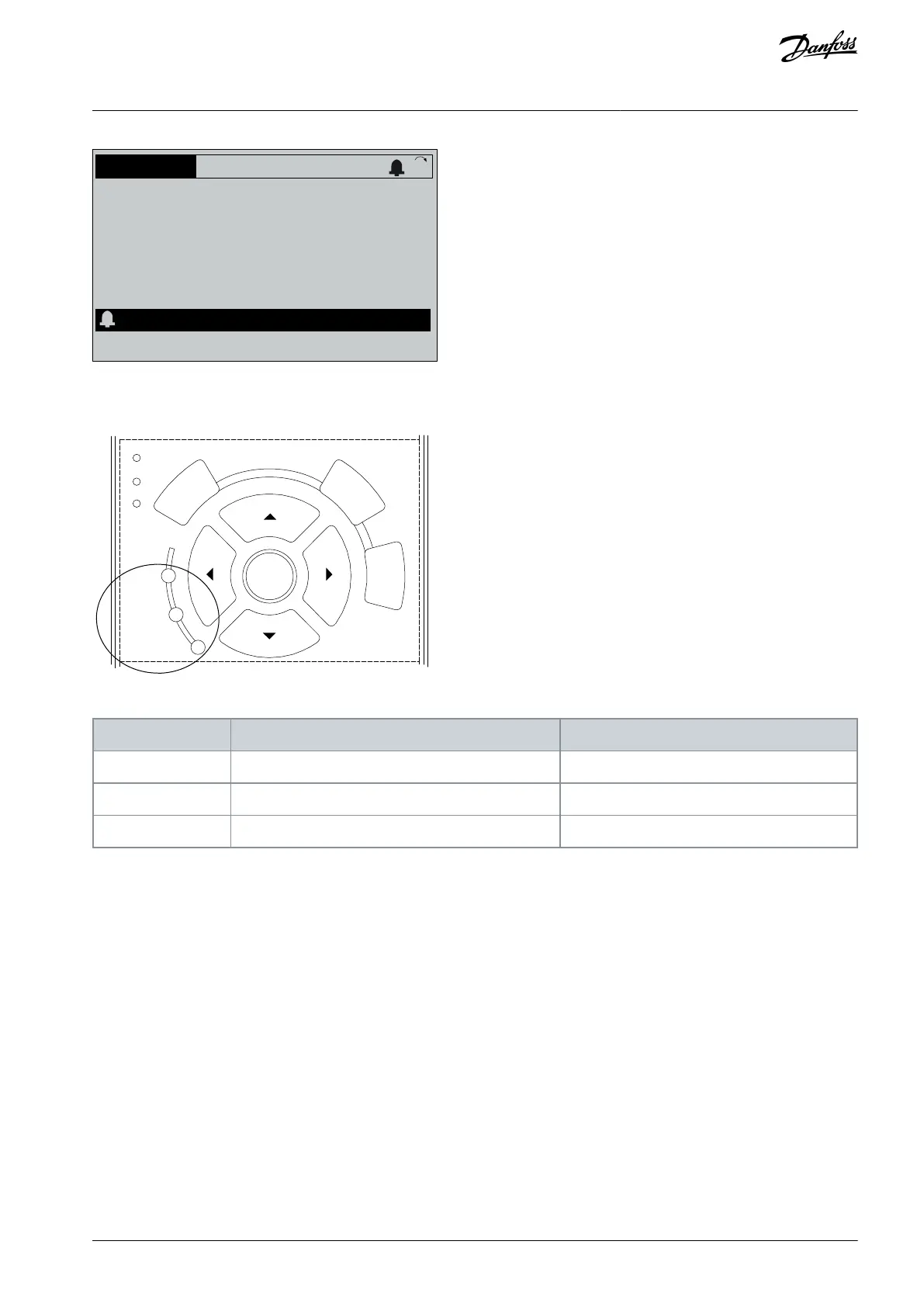
Illustration 31: Alarm Example
In addition to the text and alarm code in the LCP there are 3 status indicator lights.
Info
OK
On
Alarm
Warn.
e30bb467.12
Illustration 32: Status Indicator Lights
7.6 List of Warnings and Alarms
The following warning and alarm information defines each warning or alarm condition, provides the probable cause for the condi-
tion, and entails a remedy or troubleshooting procedure.
7.6.1 WARNING 1, 10 Volts Low
Cause
The control card voltage is less than 10 V from terminal 50. Remove some of the load from terminal 50, as the 10 V supply is overloa-
ded. Maximum 15 mA or minimum 590 Ω.
A short circuit in a connected potentiometer or incorrect wiring of the potentiometer can cause this condition.
Troubleshooting
Remove the wiring from terminal 50.
If the warning clears, the problem is with the wiring.
If the warning does not clear, replace the control card.
AQ267037536117en-000101 / 130R0083 | 67Danfoss A/S © 2023.09
Diagnostics and Troubleshooting
VLT HVAC Drive FC 102
Operating Guide
 Loading...


