2.
3.
4.
5.
6.
7.
8.
9.
10.
- a.
- b.
- c.
- d.
- e.
1.
- a.
- b.
- c.
- d.
- e.
2.
- a.
-
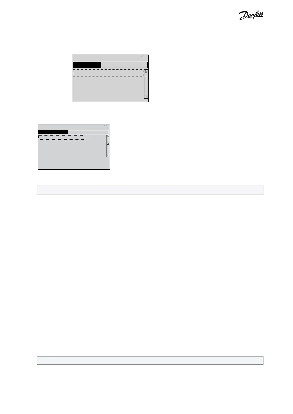
Press the navigation keys to scroll to parameter group 0-** Operation/Display and press [OK].
3-** References/Ramps
0-** Operation/Display
Press the navigation keys to scroll to parameter group 0-0* Basic Settings press [OK].
Press the navigation keys to scroll to parameter 0-03 Regional Settings and press [OK].
0-0
*
Basic Settings
0-1
*
Set-up Operations
0-2
*
LCP Display
0-3
*
LCP Custom Readout
Press the navigation keys to select [0] International or [1] North America as appropriate and press [OK].
Default settings for a number of parameters are changed.
Press [Main Menu] on the LCP.
Press the navigation keys to scroll to parameter 0-01 Language.
Select language and press [OK].
If a jumper wire is in place between control terminals 12 and 27, leave parameter 5-12 Terminal 27 Digital Input at factory
default. Otherwise, select [0] No operation in parameter 5-12 Terminal 27 Digital Input.
Make the application-specific settings in:
Parameter 3-02 Minimum Reference.
Parameter 3-03 Maximum Reference.
Parameter 3-41 Ramp 1 Ramp Up Time.
Parameter 3-42 Ramp 1 Ramp Down Time.
Parameter 3-13 Reference Site. Linked to Hand/Auto Local/Remote.
5.3.3 Asynchronous Motor Setup
Procedure
When running in flux control principle, or for optimum performance in VVC+ mode, extra motor data is required to set up the fol-
lowing parameters. Find the data in the motor datasheet (this data is typically not available on the motor nameplate). Run a com-
plete automatic motor adaptation (AMA) using parameter 1-29 Automatic Motor Adaptation (AMA)[1] Enable Complete AMA, or enter
the parameters manually. Parameter 1-36 Iron Loss Resistance (Rfe) is always entered manually.
Enter the motor data in parameter 1-20 Motor Power [kW] or parameter 1-21 Motor Power [HP] to parameter 1-25 Motor Nomi-
nal Speed. Enter the data in the following order:
Parameter 1-20 Motor Power [kW] or Parameter 1-21 Motor Power [HP].
Parameter 1-22 Motor Voltage.
Parameter 1-23 Motor Frequency.
Parameter 1-24 Motor Current.
Parameter 1-25 Motor Nominal Speed.
Motor data information is on the motor nameplate.
Enter parameters for flux control/VVC+ mode:
Parameter 1-30 Stator Resistance (Rs).
AQ267037536117en-000101 / 130R008342 | Danfoss A/S © 2023.09
Commissioning
VLT HVAC Drive FC 102
Operating Guide
 Loading...


