118 Installing System Components
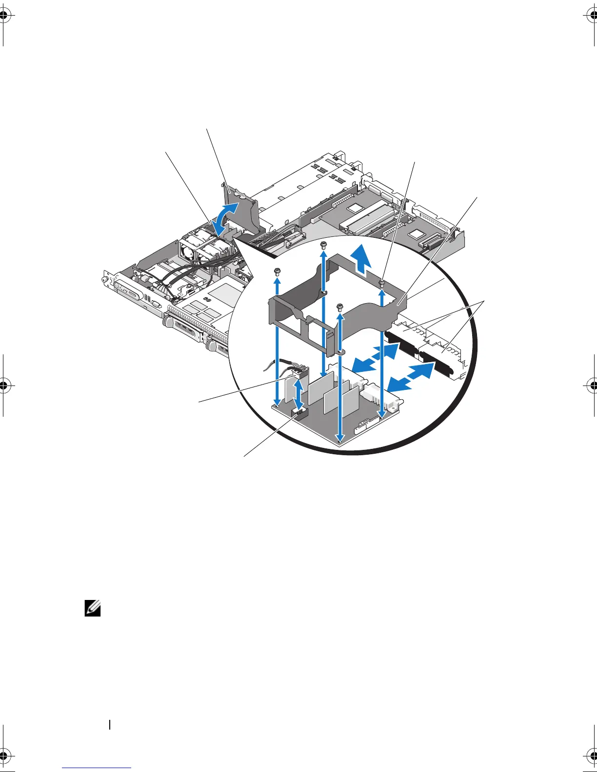
Figure 3-23. Power Distribution Board
NOTE: In the preceding figure, the 12C cable is shown connecting over the control
panel cabling. This cable should be routed under the control panel cable and the
internal USB key connector. The 12C cable seats in a cable guide clip that is directly
beneath the control panel connector.
1 power-distribution board fan module
connector
2 fan module cable connector
3 power-distribution board system bay 4 power-distribution board shroud
cover
5 shroud captive screws (4) 6 power-distribution board shroud
7 power supply connectors (2)
book.book Page 118 Sunday, June 21, 2009 5:16 PM
 Loading...