EasyManuals Logo
Home>Dell>Server>PowerEdge R300

Dell PowerEdge R300 User Manual

Dell PowerEdge R300
186 pages
To Next Page IconTo Next Page
To Previous Page IconTo Previous Page
Page #161 background imageLoading...
Page #161 background image
Jumpers and Connectors 161
Control Panel Assembly Connectors
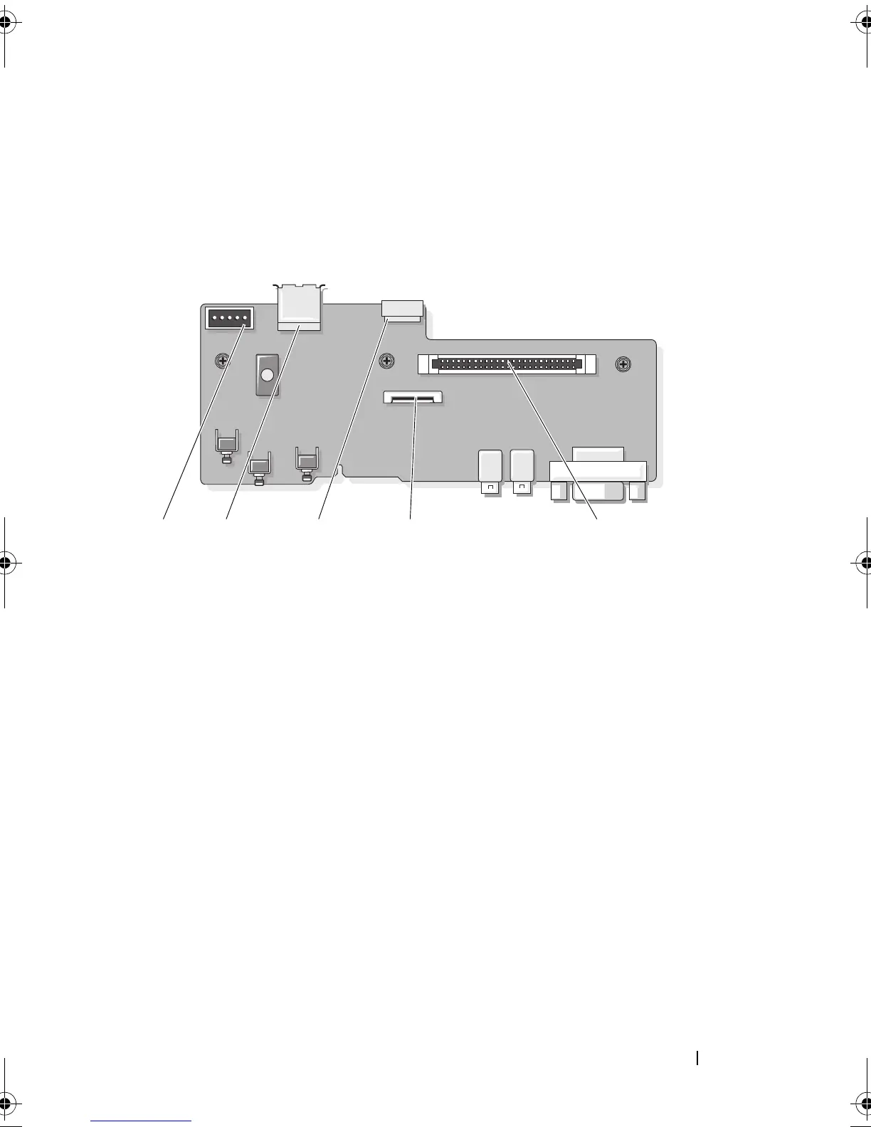
Figure 6-3 shows the configuration of the I/O control panel assembly
connectors.
Figure 6-3. Input/Output Control Panel Board
1 backplane connector (BP_12C) 2 internal USB connector (USB3)
3 internal USB key cable connector
(USB_CONN)
4 LCD panel connector (FRONT PANEL)
5 control-panel system board
connector (J_Planar)
3521 4
book.book Page 161 Sunday, June 21, 2009 5:16 PM

Table of Contents

Other manuals for Dell PowerEdge R300

Questions and Answers:

Question and Answer IconNeed help?

Do you have a question about the Dell PowerEdge R300 and is the answer not in the manual?

Dell PowerEdge R300 Specifications

General IconGeneral
BrandDell
ModelPowerEdge R300
CategoryServer
LanguageEnglish

Related product manuals