About Your System 19
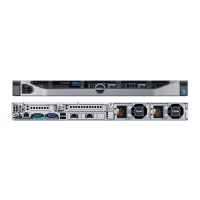
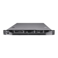
Back-Panel Features and Indicators
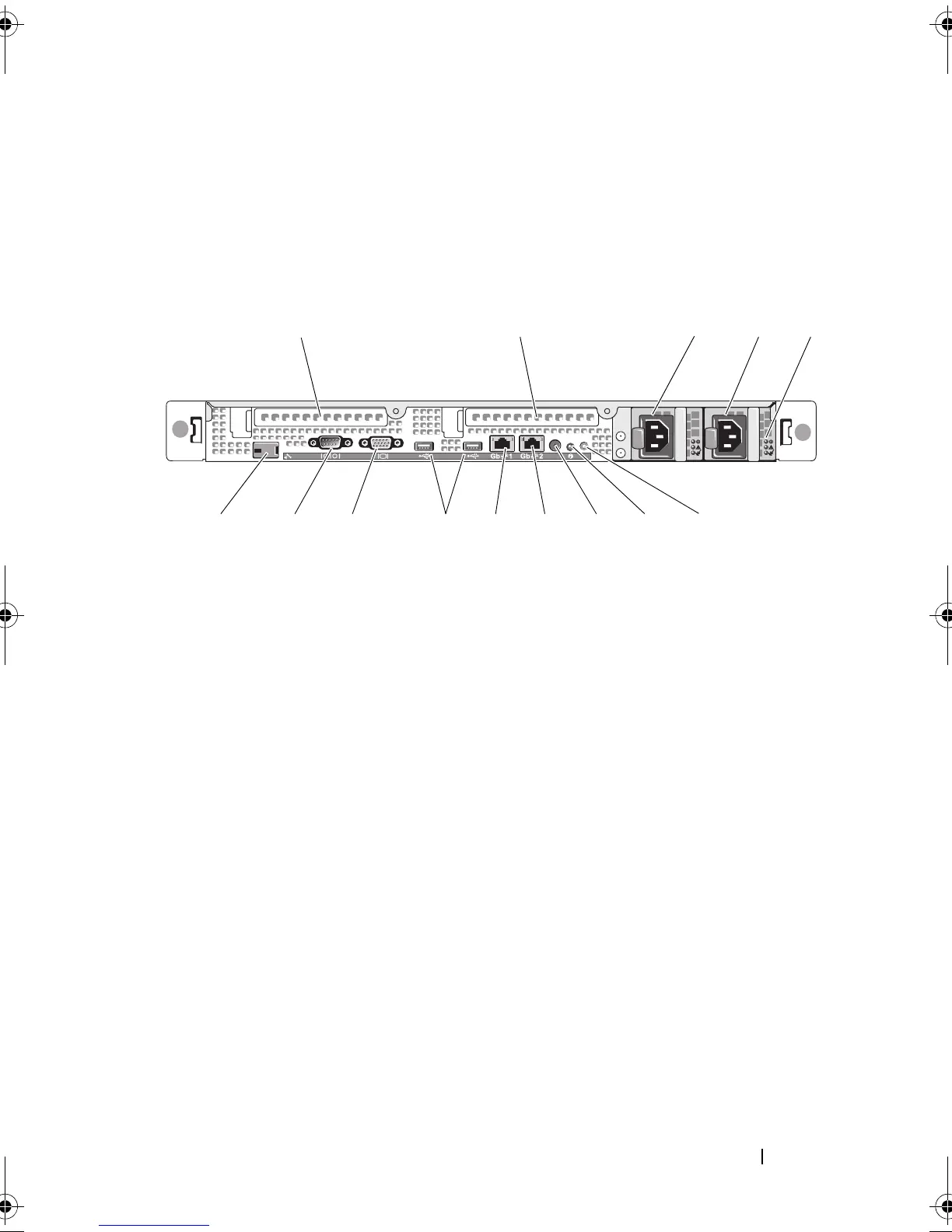
Figure 1-3 shows the controls, indicators, and connectors located on the
system's back panel.
Figure 1-3. Back-Panel Features and Indicators
Connecting External Devices
When connecting external devices to your system, follow these guidelines:
• Most devices must be connected to a specific connector and device drivers
must be installed before the device operates properly. (Device drivers are
normally included with your operating system software or with the device
itself.) See the documentation that accompanied the device for specific
installation and configuration instructions.
1 PCIe slot 1- riser card 2 PCIe slot 2 - riser card
3 power supply bay 1 (PS1) 4 power supply bay 2 (PS2)
5 redundant power supply indicators
(2)
6 system identification button
7 system status indicator 8 system status indicator connector
9 NIC2 connector (Gb) 10 NIC1 connector (Gb)
11 2.0-compliant USB connectors (2) 12 video connector
13 serial connector 14 remote access controller (RAC)
connector (optional)
book.book Page 19 Sunday, June 21, 2009 5:16 PM
 Loading...