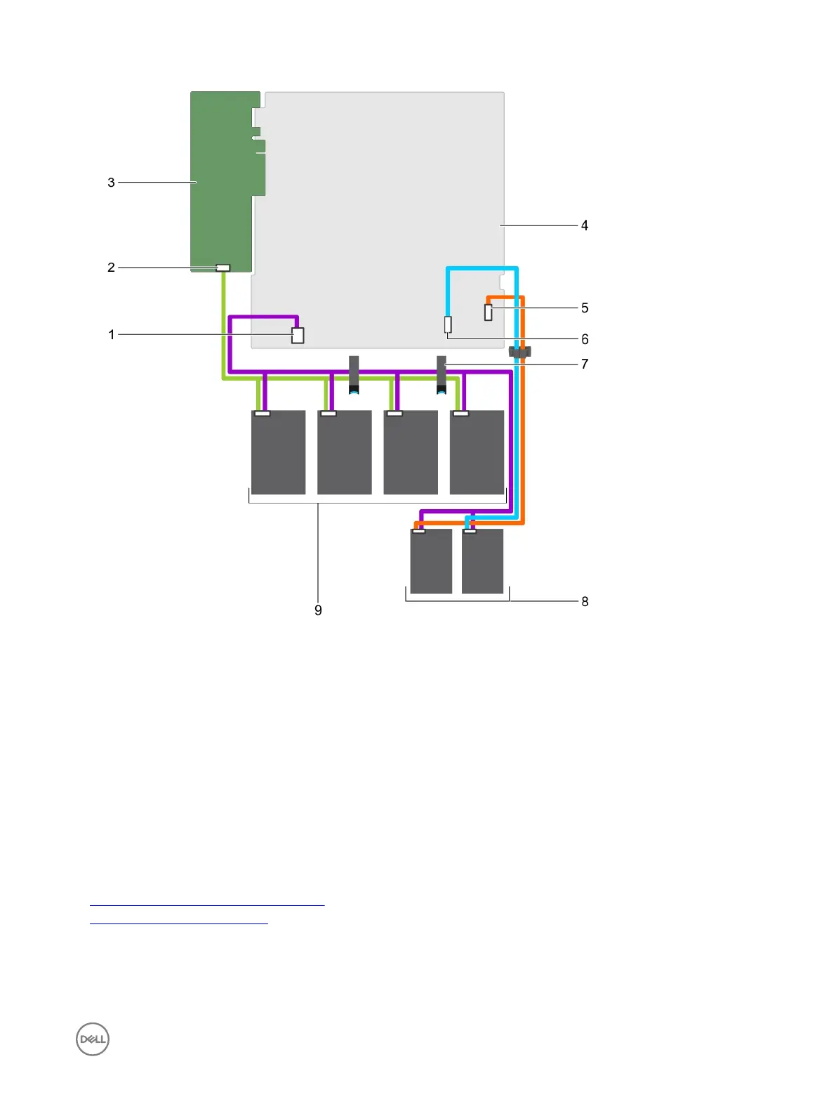
Figure 91. Cabling diagram—Four 3.5-inch cabled hard drives, two 1.8-inch SSDs, and PERC card
1.
hard drive/SSD power cable connector on the system
board
2. Connector A on the PERC card
3. PERC card 4. system board
5. optical drive/solid state drive SATA connector on the
system board
6. SATA SSD connector on the system board
7. cable routing latch 8. 1.8-inch SSD (2)
9. cabled hard drive (4)
Next steps
1. Install the hard drive backplane.
2. Follow the procedure listed in the After working inside your system section.
Related links
Removing a hot swappable hard drive carrier
Installing the hard drive backplane
129
 Loading...