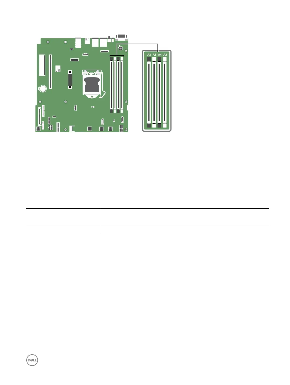
Figure 23. Memory socket locations on the system board
Memory channels are organized as follows:
Processor 1
channel 0: memory sockets A1 and A3
channel 1: memory sockets A2 and A4
The following table shows the memory populations and operating frequencies for the supported congurations:
Table 20. Memory populations and operating frequencies for the supported congurations
Memory module type Memory modules
populated per
channel
Operating frequency (in
MT/s)
Maximum memory module ranks
per channel
1.2 V
ECC (UDIMM) 1 1600, 1866, 2133, 2400 Dual rank or single rank
2 1600, 1866, 2133, 2400 Dual rank or single rank
General memory module installation guidelines
Your system supports Flexible Memory Conguration, enabling the system to be congured and run in any valid chipset architectural
conguration. The following are the recommended guidelines for installing memory modules:
• x4 and x8 DRAM-based DIMMs can be mixed.
• Up to two dual- or single-rank ECC UDIMMs can be populated per channel.
• Populate DIMM sockets only if a processor is installed. For single-processor systems, sockets A1 to A4 are available.
• Populate all sockets with white release levers rst, and then all the sockets with black release levers.
• When mixing memory modules with dierent capacities, populate the sockets with memory modules with the highest capacity
rst. For example, if you want to mix 4 GB and 8 GB DIMMs, populate 8 GB DIMMs in the sockets with white release levers and
4 GB DIMMs in the sockets with black release levers.
• Memory modules of dierent capacities can be mixed provided other memory population rules are followed (for example, 4 GB
and 8 GB memory modules can be mixed).
• Mixing of more than two DIMM capacities in a system is not supported.
61
 Loading...