AH Motion Controller – Hardware Manual
4-20
4
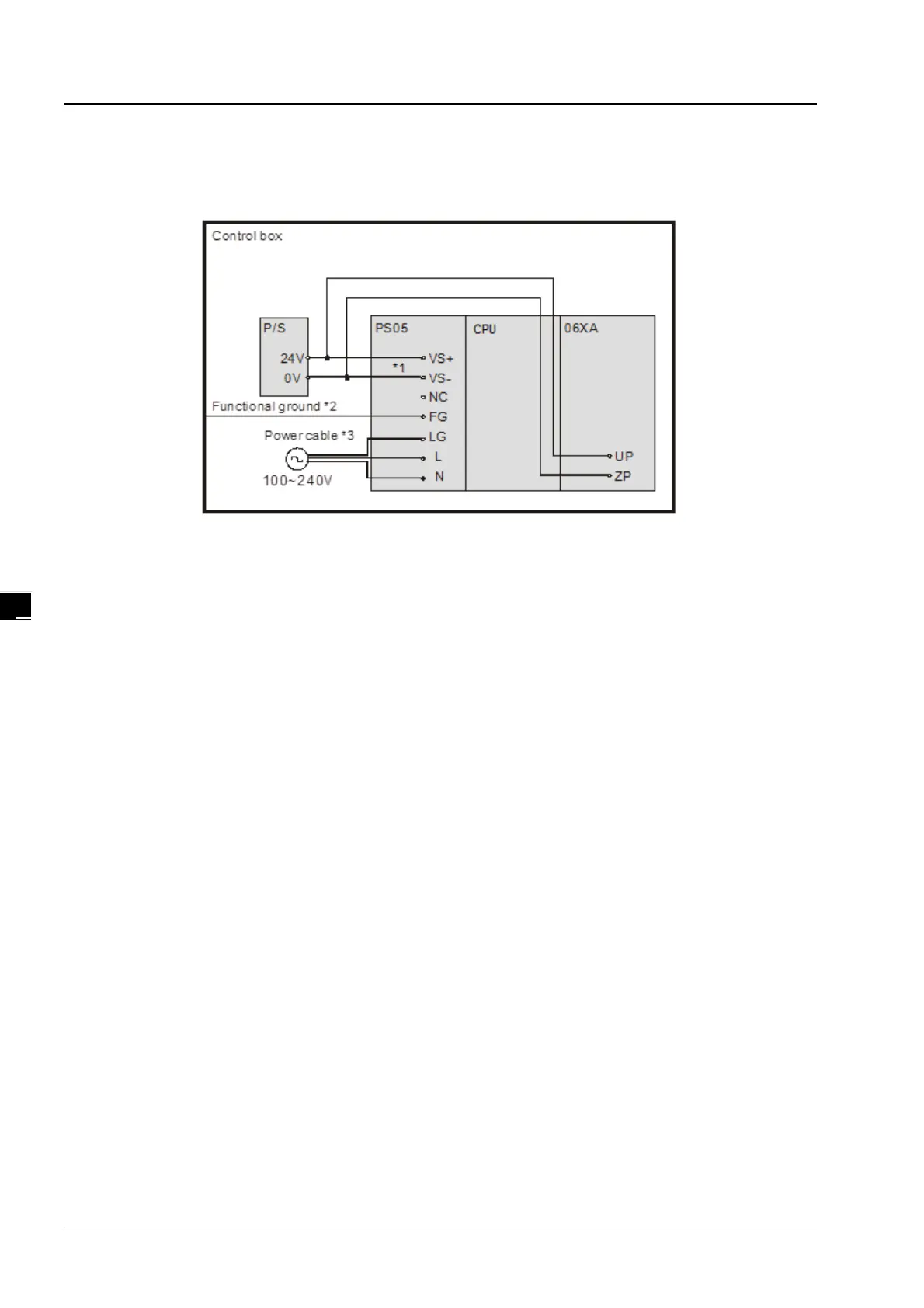
4.5.3 Wiring Power Supply Modules
Connecting an AC power cable
*1. 24V on the external power supply is connected to VS+ and VS- on the power supply module. VS+ and VS- can be
used to detect whether the voltage of the external power supply is stable.
*2. FG on the power supply module is connected to the control box as the functional ground.
*3. The live wire and the neutral wire in the AC power cable are connected to L and N on the power supply module
respectively. To prevent the system from becoming abnormal, the ground in the AC power cable has to be
connected to LG on the power supply module.
The power input of AHPS05-5A is the AC input. You have to pay attention to the following points when you use
AHPS05-5A.
The alternating-current input voltage is in the range of 100 VAC to 240 VAC. Please connect the power supply to
the terminals L and N. If the 110 VAC or the 220 VAC power supply is connected to the input terminals VS+ and
VS-, the PLC will be damaged.
In order to ensure that the external power supply stably provides24 VDC power, the external power supply can be
connected to VS+ and VS-. If the PLC detects that the voltage of the external power supply is lower than the
working voltage, you can write a protective program.
The length of the cable connecting with the ground should be more than 1.6 millimeters.
If the power cut lasts for less than 10 milliseconds, the PLC keeps running without being affected. If the power cut
lasts for long, or if the voltage of the power supply decreases, the PLC stops running, and there is no output. When
the power supply returns to normal, the PLC resumes. (You have to notice that there are latched auxiliary relays
and registers in the PLC when you write the program.)
Please use single-core cables or multicore cables. The diameters of the cables used should be in the range of 12
AWG to 22 AWG. The torque applied to the terminal screws should be 9.50 kg-cm (8.25 Ib-in). Please use copper
conducting wires. The temperature of the copper conductive cables should be 60/75°C.

 Loading...

