Chapter 4 Installation & Wiring
52
:LULQJ,QIRUPDWLRQ8VHDGHTXDWHZLUHJDXJH
1
), copper wires with temperature
UHVLVWDQFHXSWR&DQGOELQWRUTXHIRUFH
2
) when connecting to AC and DC
wiring terminals.
Model Wiring Location Wire Gauge (
*
1
) Bolt Type Torque (lb-in) (
*
2
)
GES104NT,
NT-100K
Main Input 4/0 AWG X 1 M10 220±8
Res. Input 2/0 AWG X 2 M10 220±8
Output 2/0 AWG X 2 M10 220±8
Battery 2/0 AWG X 2 M10 220±8
PE 3 AWG X 1 M10 220±8
4.9 Electrical Connections
WARNING:
1. AC power source connection: Three-phase (R/ S/ T) of AC power source
PXVWEHLQSRVLWLYHSKDVHVHTXHQFHDQGWKH5671FDEOHVPXVWEH
FRQQHFWHGWRWKHWHUPLQDOVµ5¶µ6¶µ7¶µ1¶VKRZQLQWKHIROORZLQJ¿JXUHV
2. Battery source connection: The positive and negative poles of the battery
FDELQHWPXVWEHFRQQHFWHGWRWKHWHUPLQDOSROHVµ¶DQGµ¶VKRZQLQWKH
IROORZLQJ¿JXUHV
3. The external battery cabinet must be grounded and connected to the
836¶Vµ%DWWHU\&DELQHW*URXQG¶WHUPLQDO'RQRWFRQQHFWWKHH[WHUQDO
battery cabinet to any other grounding system.
4. Wrong wiring will cause damage to the UPS and electric shock.
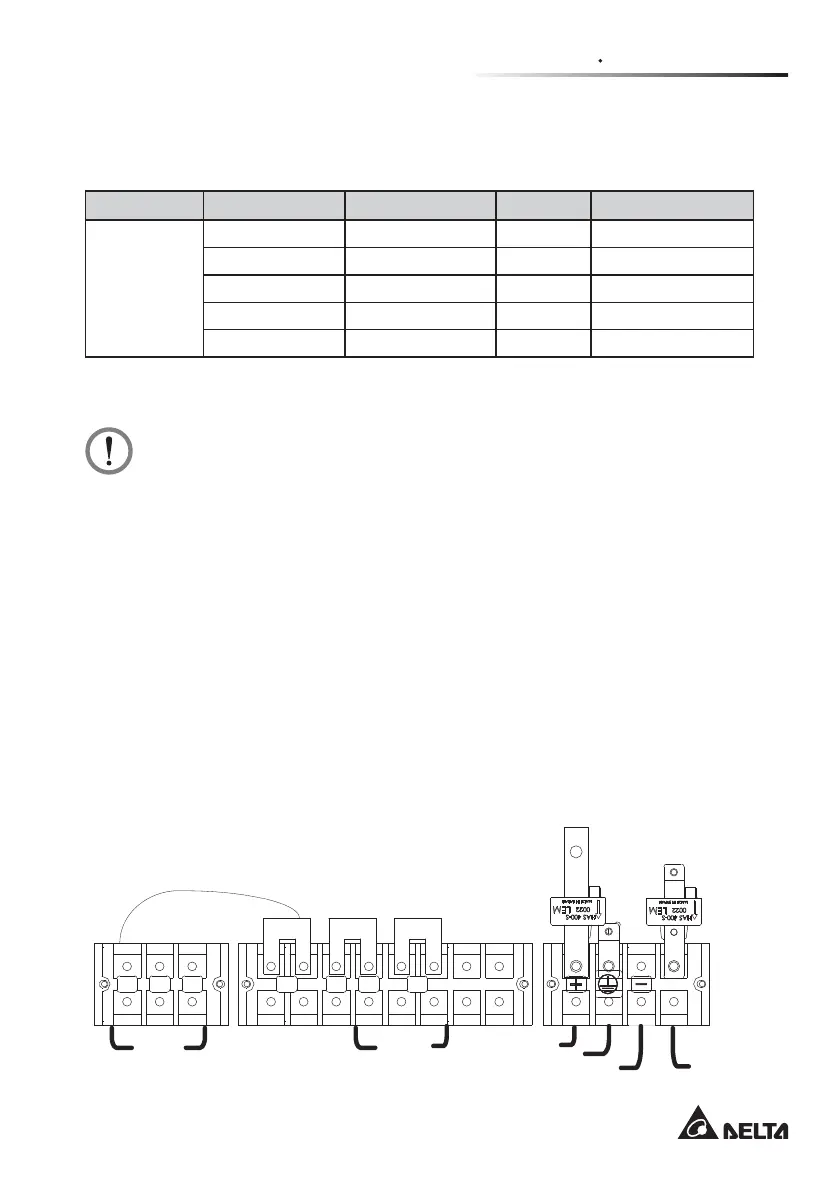
4.9.1 10~30kVA Output 220Vac Terminal Wiring Diagram
Single input: When there is only one input source, the wiring diagram is as follows.
R
S
TRNNR
Input Output
1B
Battery
Cabinet
Ground
Battery+
Battery -
Ground
 Loading...